Electrical Rotating Machine Comprising an Intermediate Sleeve Interposed Between the Shaft and the Polar Wheels and Method for Making the Rotor

a technology of electric rotating machines and polar wheels, which is applied in the direction of dynamo-electric machines, electrical apparatus, magnetic circuits, etc., can solve the problems of not being able to achieve a sufficiently precise concentricity of pole pieces and/or cores with respect to the rotation axis, risk of damage, and not being able to uniformly penetrate. , to achieve the effect of easy machined external periphery and good concentricity of sleeves or sleeves

Inactive Publication Date: 2008-12-25
VALEO EQUIP ELECTRIC MOTEUR
View PDF22 Cites 24 Cited by
  • Summary
  • Abstract
  • Description
  • Claims
  • Application Information

AI Technical Summary

Benefits of technology

[0026]In addition it is possible easily to machine the external periphery of the intermediate sleeve or sleeves in order to have good concentricity of the sleeve or sleeves with respect to the axis of the shaft, the pole pieces being machine

Problems solved by technology

However, in these two known embodiments, the driving portion of the shaft, and in particular the serrations, do not make it possible to obtain a sufficiently precise concentricity of the pole pieces and/or of the core with respect to the rotation axis of the shaft.
This is because it is found that the serrations do not uniformly penetrate the central bores of the pole pieces and core.
During this machining operation, hot shavings are liable to be thrown onto the winding, which thus risks being damaged.
In addition, this machining operation cannot be carried out using a lubricant, which also risks damaging the coil.
The machining operation is therefore made more lengthy and more expensive.
Moreover, the force necessary for axially pressing the pole pieces against each other does not make it possi

Method used


Image

  • Electrical Rotating Machine Comprising an Intermediate Sleeve Interposed Between the Shaft and the Polar  Wheels and Method for Making the Rotor
  • Electrical Rotating Machine Comprising an Intermediate Sleeve Interposed Between the Shaft and the Polar  Wheels and Method for Making the Rotor
  • Electrical Rotating Machine Comprising an Intermediate Sleeve Interposed Between the Shaft and the Polar  Wheels and Method for Making the Rotor

Examples


first embodiment

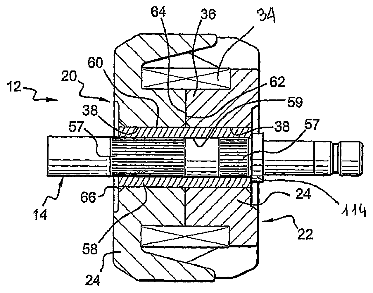
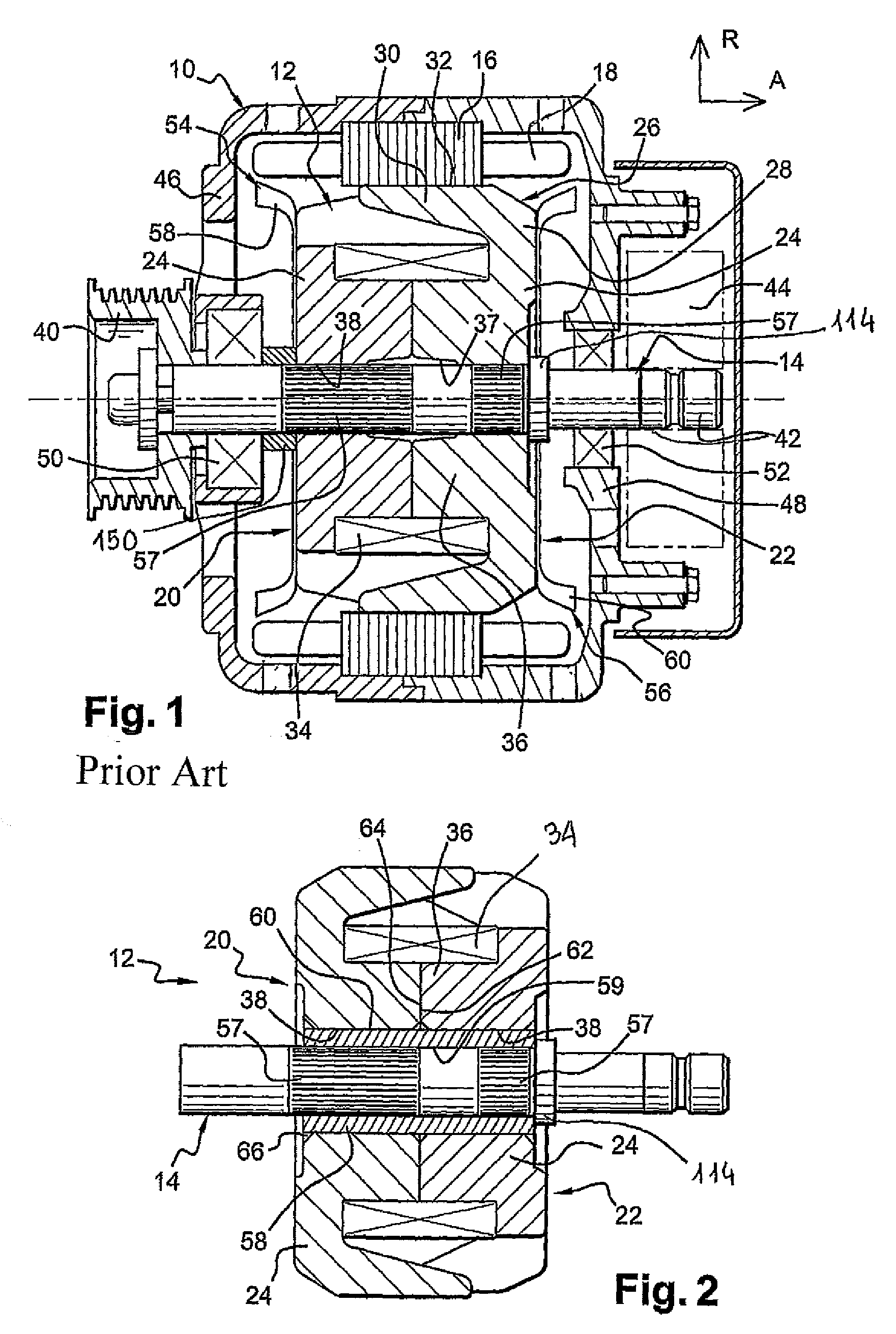
[0123]According to the invention that is depicted in FIG. 2, the rotor 12 is similar to the rotor 12 depicted in FIG. 1. The rotor 12 thus comprises a central shaft 14, two pole pieces 20, 22 that are arranged axially on each side of a core 36, and an excitation coil 34 that extends radially around the core 36.

[0124]However, the rotor 12 comprises here an intermediate sleeve 58 that comprises a central fixing bore 59. The driving portions 57 of the shaft 14 are force-fitted in the fixing bore 59 of the sleeve 58.

[0125]These portions 57 comprise reliefs in the form of serrations belonging to a knurling.

[0126]The sleeve 58 comprises a cylindrical surface 60, here axially oriented, that merges here with the external peripheral cylindrical surface of the sleeve 58. The surface 60, which is by virtue of the invention coaxial as described below with the rotation axis of shaft 14, is intended to receive the pole pieces 20, 22.

[0127]According to this embodiment of the invention, the sleeve ...

second embodiment

[0197]According to the invention depicted in FIG. 5, the shaft 14 is directly fitted in the hub 158 and therefore in the central part thereof formed by the core 36.

[0198]The rotor 12 comprises here, in the aforementioned manner, two intermediate sleeves 58 that are arranged axially on each side of the core 36 and that are produced in one piece with the core 36, and in which the driving portion or portions 57 of the shaft 14 is or are fitted.

[0199]The outside diameter of the core 36 is greater than the outside diameter of the surface 60 of each sleeve 58. Thus the core 36 comprises two external end radial faces 70, 72 that project radially with respect to the sleeves 58 and delimit the axial ends of the core 36.

[0200]The surface 60 of each sleeve 58 is fitted in the central bore 138 of the associated pole piece 20, 22 so that the internal radial face 74 of the flange 24 of the pole piece 20, 22, delimiting respectively the rear axial end and the front axial end of the pole piece 20, ...

third embodiment

[0216]In a third embodiment depicted in FIG. 6, the two driving portions 157, 257 of the central shaft 14 are shorter axially as in the aforementioned variant and, as in FIGS. 2 and 3, the core of the claw rotor 12 comprises two portions 36a, 36b.

[0217]A sleeve respectively 258, 358 is associated with each portion of the core 36a, 36b.

[0218]The sleeves 258, 358 are externally smooth and are in a single piece with the central shaft 14. These sleeves 258, 358 therefore issue from the shaft 14 and have different outside diameters, just like the driving portions 157, 257.

[0219]Each portion 157, 257 axially extends respectively the sleeve 258, 358.

[0220]The portion 157 is adjacent to the collar 114.

[0221]The outside diameter of the driving portion 257 is roughly equal to the outside diameter of the sleeve 258.

[0222]The outside diameter of the sleeve 258 is less than the outside diameter of the driving portion 157.

[0223]The outside diameter of the sleeve 358 is less than the outside dia...


PUM

PropertyMeasurementUnit
Forceaaaaaaaaaa
Diameteraaaaaaaaaa

Abstract

An electrical rotating machine rotor, in particular for a motor vehicle, comprising a central shaft, an annular core coaxial with the shaft and two polar wheels which are axially arranged on either side of the core, of the type wherein the shaft includes at least one drive section which is axially force-fitted into a fixing bore of at least one component of the rotor so as to secure in rotation at least one of the two polar wheels of the rotor to the shaft, an intermediate sleeve being radially interposed between each polar wheel and the central shaft, and on which sleeve is mounted said polar wheel. The invention also concerns a method for making such a rotor.

Description

FIELD OF THE INVENTION[0001]The invention concerns a rotor for a rotary electrical machine, such as an alternator or an alternator-starter, in particular for a motor vehicle.BACKGROUND OF THE INVENTION[0002]The invention concerns more particularly a rotor for a rotary electrical machine, such as an alternator or an alternator-starter, in particular for a motor vehicle, which comprises:[0003]a central shaft;[0004]an annular core coaxial with the shaft;[0005]a coil that extends radially around the core;[0006]and two pole pieces that are arranged axially on each side of the core and coil;of the type in which the shaft comprises at least one driving portion whose cross section, along a radial plane, is not smooth, and which is axially force-fitted in a bore for fixing at least one component of the rotor so as to rotationally fix at least the two pole pieces of the rotor to the shaft.[0007]Rotors of this type are already known in which the core is divided axially into two distinct portio...

Claims


Application Information

Patent Timeline
IPC IPC(8): H02K1/30H02K15/02
CPCH02K1/243Y10T29/49012H02K15/16H02K1/30H02K3/528H02K2203/12H02K1/24
Inventor BADEY, JEAN-PHILIPPELENOIR, ROMARICTUNZINI, MARCBILTERYST, PIERRE-YVES
Owner VALEO EQUIP ELECTRIC MOTEUR
Why Eureka
Try Eureka