Flat Panel Lens

a flat panel and lens technology, applied in waveguides, instruments, lighting and heating apparatuses, etc., can solve the problems of less well working with skew rays, picture banding, and bulky conventional optical systems, and achieve the effect of avoiding discontinuities and being more compa

a flat panel and lens technology, applied in waveguides, instruments, lighting and heating apparatuses, etc., can solve the problems of less well working with skew rays, picture banding, and bulky conventional optical systems, and achieve the effect of avoiding discontinuities and being more compa

US20080316768A1Active Publication Date: 2008-12-25MICROSOFT TECH LICENSING LLC

Image

  • Flat Panel Lens
  • Flat Panel Lens
  • Flat Panel Lens

Examples


Embodiment Construction

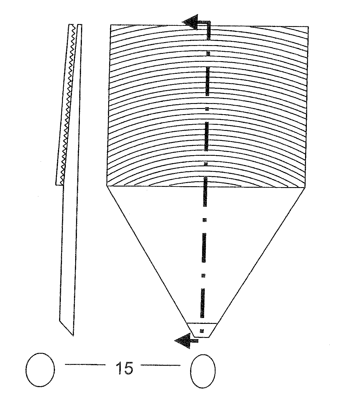
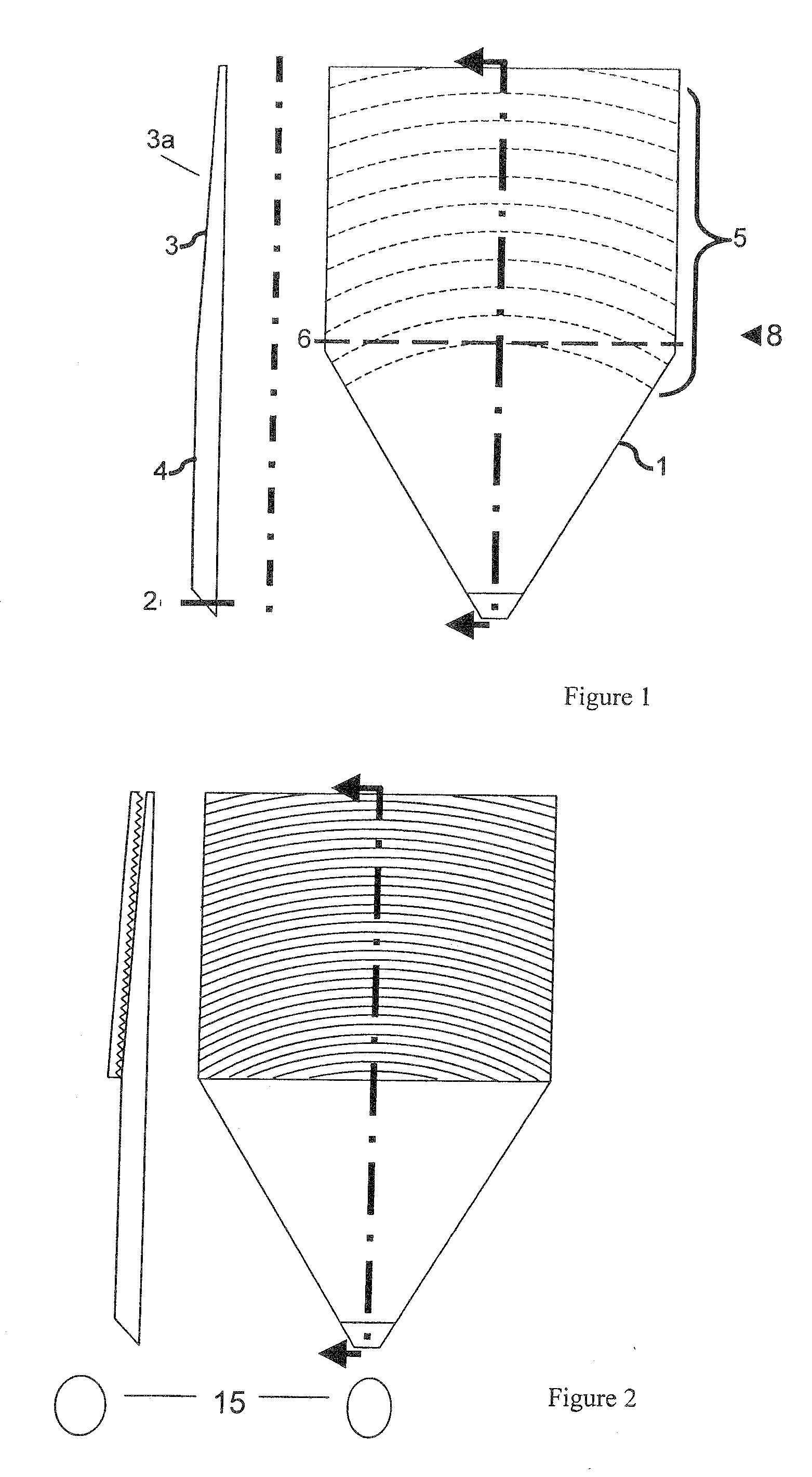
[0014]FIG. 1 shows a flat lens generally indicated at 1, consisting of a circular-sector-shaped input region 4 and a tapered output region 3. For use in reverse, e.g. in a camera, the roles of these two parts are reversed but for convenience “input” and “output” will be used as labels. Light is input (or output, depending on direction) at a point generally indicated at 2, which is a small beveled face on the tip of the input region 4. This region is a parallel-face slab which in plan has the shape of an isosceles triangle or circular sector. The output region 3 with its output face 3a adjoins this input region, having initially the same thickness, but tapers down, as shown in the sectional view, according to the radial distance r from the input point 2. This taper can be uniform, as described in WO 01 / 72037, or, preferably, of a profile such as to keep the total number of bounces constant, as described in WO 03 / 13151. Input and output regions 4 and 3 can be made of one piece of the ...


PUM


Abstract

A light guide with input and output faces 2, 3a is polar-symmetric about the first face 2 and has optical properties such that the angle at which a ray is injected into the first face determines the position at which it leaves the second face 3a, or, if operated in the reverse direction, the position at which the ray enters the second face determines the angle at which the ray leaves the second face. The light guide includes a tapered transparent sheet 3, light from the first face entering at the thick end of this sheet, and the second face forming one face of the tapered sheet. An input / output slab 4 adjoins the tapered sheet 3 for fan-out of light from the first face 2 to the tapered sheet, and a transition region 8 is located between flat and tapered sheets. The polar symmetry means that light rays always travel in line with the taper direction, which suppresses banding. Preferably the light guide further includes a prism device 20 for folding the light so that the flat and tapered sheets can be folded over each other. A method of making such a prism is also disclosed.

Description

[0001]This invention is concerned with lenses in general and aims largely to eliminate the space normally required between a lens and its focal point.FIELD OF THE INVENTION[0002]Lenses are commonly used to focus collimated light to a point, as in cameras, or to collimate light emerging from a point, as in car headlights. The focal point is some distance behind the lens, and space is required in order to allow rays from the point to fan out to the lens diameter or vice versa. This makes conventional optical systems bulky.[0003]An example of this problem is in the design of rear-projection televisions, which are less expensive than plasma displays or liquid crystal displays, but are bulky. WO 01 / 72037 describes how to make a thin projection display by pointing a video projector into the thick end of a wedge-shaped light-guide. The light is totally internally reflected between the two faces of the wedge as it travels towards the sharp end, bouncing at progressively steeper angles. At a...

Claims


Application Information

Patent Timeline
25 Dec 2008
Publication
US20080316768A1
IPC
F21V7/04; F21V11/00; G02B5/04; F21V8/00; G02B6/00; G02B27/09
CPC
G02B6/0011; G02B6/0046; G02B6/0053; G02B27/0994; Y10S385/901; G02B6/00; G02B6/0001; G05B5/04
Inventors
TRAVIS, ADRIAN R. L.