Modified Pre-Ferrulized Communication Cable Assembly and Installation Method

a technology of pre-ferrulized communication cable and assembly, which is applied in the direction of optics, instruments, optical light guides, etc., can solve the problems of not being able to pass such a cable assembly, remaining difficult to pass a partially completed cable assembly, and not being able to recommend a technique, etc., to achieve the effect of facilitating cable installation, facilitating the passage of pre-ferrulized cable assembly, and minimizing the bend radius

Active Publication Date: 2008-12-25
DRAKA COMTEQ BV
View PDF13 Cites 87 Cited by
  • Summary
  • Abstract
  • Description
  • Claims
  • Application Information

AI Technical Summary

Benefits of technology

[0011]The pre-ferrulized cable assembly is characterized in that, to make it possible to pass the communication cable through narrow cable guide, the optical fiber is exposed at the free, front end of the communication cable. This free end of the cable is fixedly surrounded by a connecting element, which can be mechanically connected to one or more complementary sleeves to complete the communication connector after the communication cable has been passed through the cable guide from a start position to an end position.
[0046]The pre-ferrulized cable assemblies of the present invention not only reduce the time and effort required to install optical cables in an end user's home, but also reduce the need for subsequent home visits. Blowing of the pre-ferrulized cable assemblies of the present invention through narrow cable guides (e.g., a cable guide having an outside diameter of about 4 millimeters and inside diameter of about 3 millimeters) is possible even for cable guides longer than 1,000 meters.

Problems solved by technology

This is not an advisable technique, however, because it is necessary to expose the optical fiber by removing the cable sheath, to mount the exposed optical fiber end in the connector, and to polish the end face of the optical fiber so as to enable a good signal transmission.
In addition, it is difficult to pass such a cable assembly (i.e., having a complete connector mounted to the free, front end of the communication cable) through the cable guide.
This makes it necessary to carry out operations at the end position (e.g., in the end user's home), which is undesirable in view of the extent of planning and the man-hours involved.
Despite the installation efficiencies of the cable assemblies disclosed in U.S. patent application Ser. No. 11 / 747,573, passage of a partially completed cable assembly remains difficult, if not impossible, through sharp bends in narrow cable guides.

Method used


Image

  • Modified Pre-Ferrulized Communication Cable Assembly and Installation Method
  • Modified Pre-Ferrulized Communication Cable Assembly and Installation Method
  • Modified Pre-Ferrulized Communication Cable Assembly and Installation Method

Examples


examples

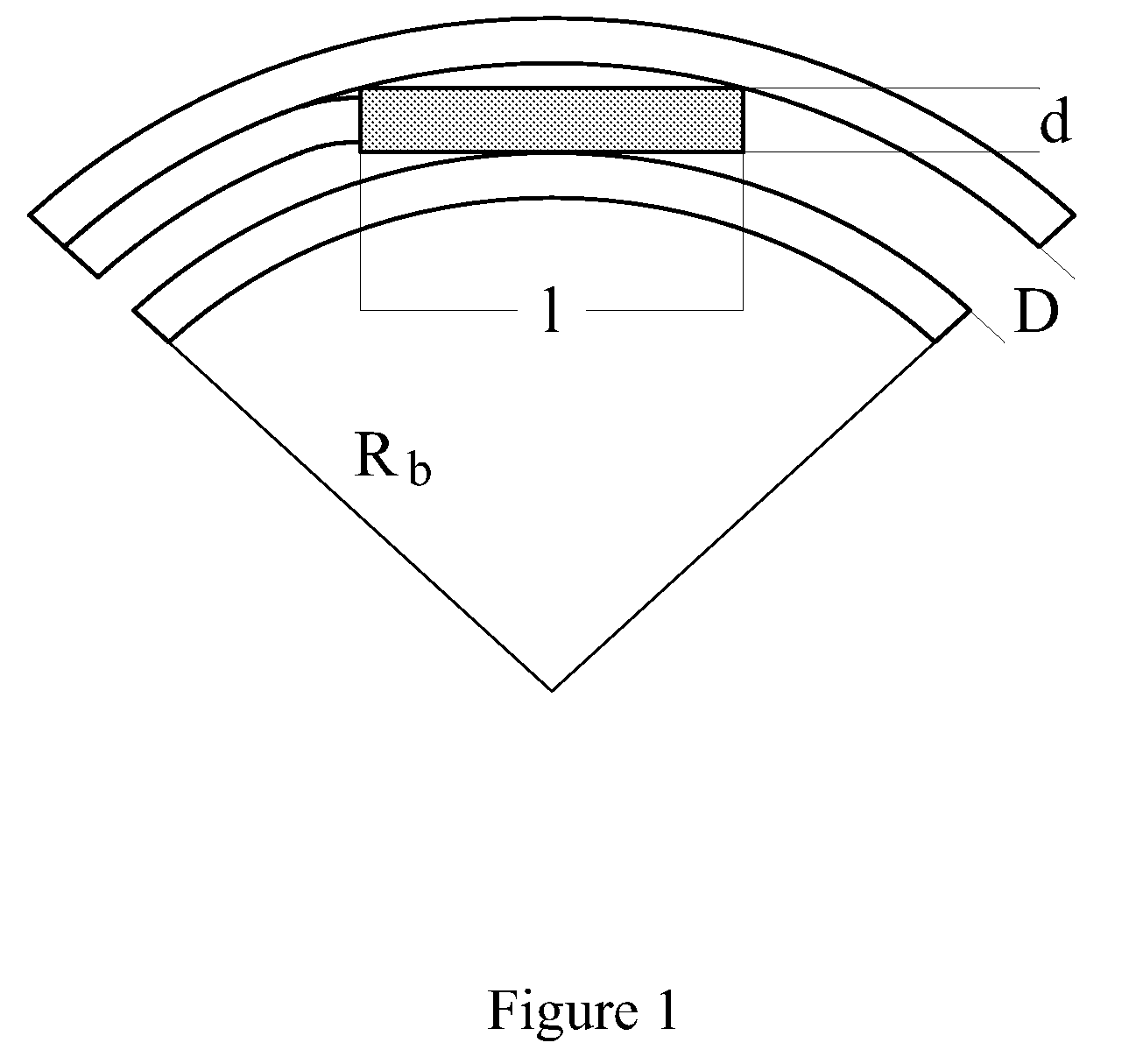
[0108]For testing various cables assemblies, a microduct (i.e., cable guide) having a length of 100 meters and an outside diameter of about 4 millimeters and an inside diameter of about 3 millimeters (e.g., having a millimeter diameter ratio of about 4 / 3) was laid on the ground in 10-meter loops. Each loop included a 180° bend with a bend radius of about 20 centimeters. At around 50 meters (i.e., about midway through the microduct), a sharper bend was made with the microduct in a bench vice, in which the bend radius (twice the plate-distance inside the bench vice) could be varied. (In this regard, the bend radius in two-point bending is a little less than half the plate distance.) Each cable assembly was blown using a MicroJET EM-25 with an air pressure of 10 bar and the magnetic clutch at position 4 (i.e., with a 15 N pushing force).

[0109]First, a bare cable with a short conical end-cap was tested through the aforementioned microduct. The cable passed a minimum bend radius of 35 mi...


PUM

PropertyMeasurementUnit
bend radiusaaaaaaaaaa
inner diameteraaaaaaaaaa
diameteraaaaaaaaaa

Abstract

Disclosed is a modified pre-ferrulized cable assembly that facilitates installation of an optical fiber communication cable through narrow cable guides having sharp bends. The pre-ferrulized cable assembly includes a communication cable having a free, front end, a semi-finished communication connector, and a suction plug. The invention further relates to efficient methods for installing the modified pre-ferrulized cable assembly through a cable guide.

Description

CROSS-REFERENCE TO PRIORITY APPLICATIONS[0001]This application is a continuation-in-part of commonly assigned U.S. patent application Ser. No. 11 / 747,573, for Communication Cable Assembly and Installation Method, filed May 11, 2007, (and published Nov. 15, 2007, as U.S. Patent Application Publication No. US 2007 / 0263960 A1). U.S. patent application Ser. No. 11 / 747,573 itself claims the benefit of Dutch Application No. 1,031,792 (filed May 11, 2006 at the Dutch Patent Office).[0002]This application hereby (i) claims the benefit of U.S. patent application Ser. No. 11 / 747,573 and Dutch Application No. 1,031,792, and (ii) incorporates entirely by reference Dutch Application No. 1,031,792, U.S. patent application Ser. No. 11 / 747,573, and U.S. Patent Application Publication No. US 2007 / 0263960 A1.[0003]This application further claims the benefit of commonly assigned U.S. Provisional Patent Application Ser. No. 60 / 969,401, for Modified Pre-Ferrulized Communication Cable Assembly and Instal...

Claims


Application Information

Patent Timeline
Patent Type & Authority Applications(United States)
IPC IPC(8): G02B6/40
CPCG02B6/3887G02B6/4464Y10T29/49826Y10T29/49174G02B6/38875G02B6/52
Inventor GRIFFIOEN, WILLEMLOCK, PIETER
Owner DRAKA COMTEQ BV
Why Eureka
Try Eureka