Power loss reduction in turbulent wind for a wind turbine using localized sensing and control

a wind turbine and wind power technology, applied in the field of wind power turbines, can solve problems such as power loss reduction, and achieve the effect of reducing the

Inactive Publication Date: 2008-12-25
GENERAL ELECTRIC CO
View PDF8 Cites 96 Cited by
  • Summary
  • Abstract
  • Description
  • Claims
  • Application Information

AI Technical Summary

Benefits of technology

[0005]Embodiments of the present invention are directed to localized sensing and actuation systems to reduce the effect of angle of attack deviation (from the planned / controlled value) on power and loads in turbulent winds. One embodiment is directed to a wind turbine comprising: a wind turbine blade disposed on the wind turbine, the blade being configured to rotate about an axis upon an impact of a wind flow on the blade; at least one load sensor disposed on or within the blade, the at least one load sensor configured to measure local loading on the blade due to local wind inflow sensed at the at least one load sensor; and at least one active flow modification device disposed on the blade, the at least one active flow modification device configured to modify the wind flow proximate to the blade, and wherein the at least one active flow modification device is configured to receive active flow modification instructions based on the at least one sensor local loading measurements.
[0007]Yet another embodiment of the present invention is directed to a wind turbine blade assembly comprising at least one local load sensor disposed on or within a surface of the wind turbine blade and at least one active flow modification device disposed on or within a surface of the wind turbine blade and configured to alter the aerodynamics of the wind turbine blade in response to local load sensor measurements such that a difference between a current angle of attack and an optimum angle of attack is substantially minimized.

Problems solved by technology

Maximizing wind turbine performance while minimizing system loads in given wind conditions is one of the many challenges that exist in harnessing wind energy.

Method used


Image

  • Power loss reduction in turbulent wind for a wind turbine using localized sensing and control
  • Power loss reduction in turbulent wind for a wind turbine using localized sensing and control
  • Power loss reduction in turbulent wind for a wind turbine using localized sensing and control

Examples


Embodiment Construction

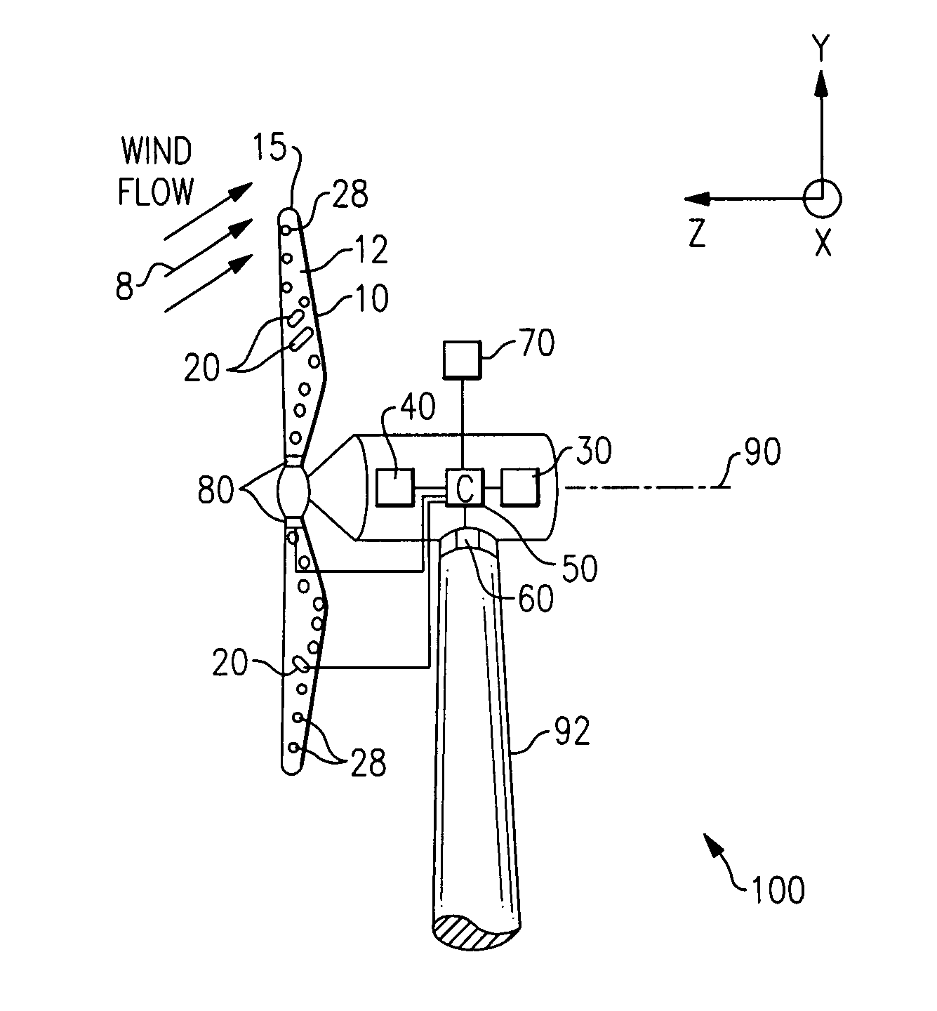
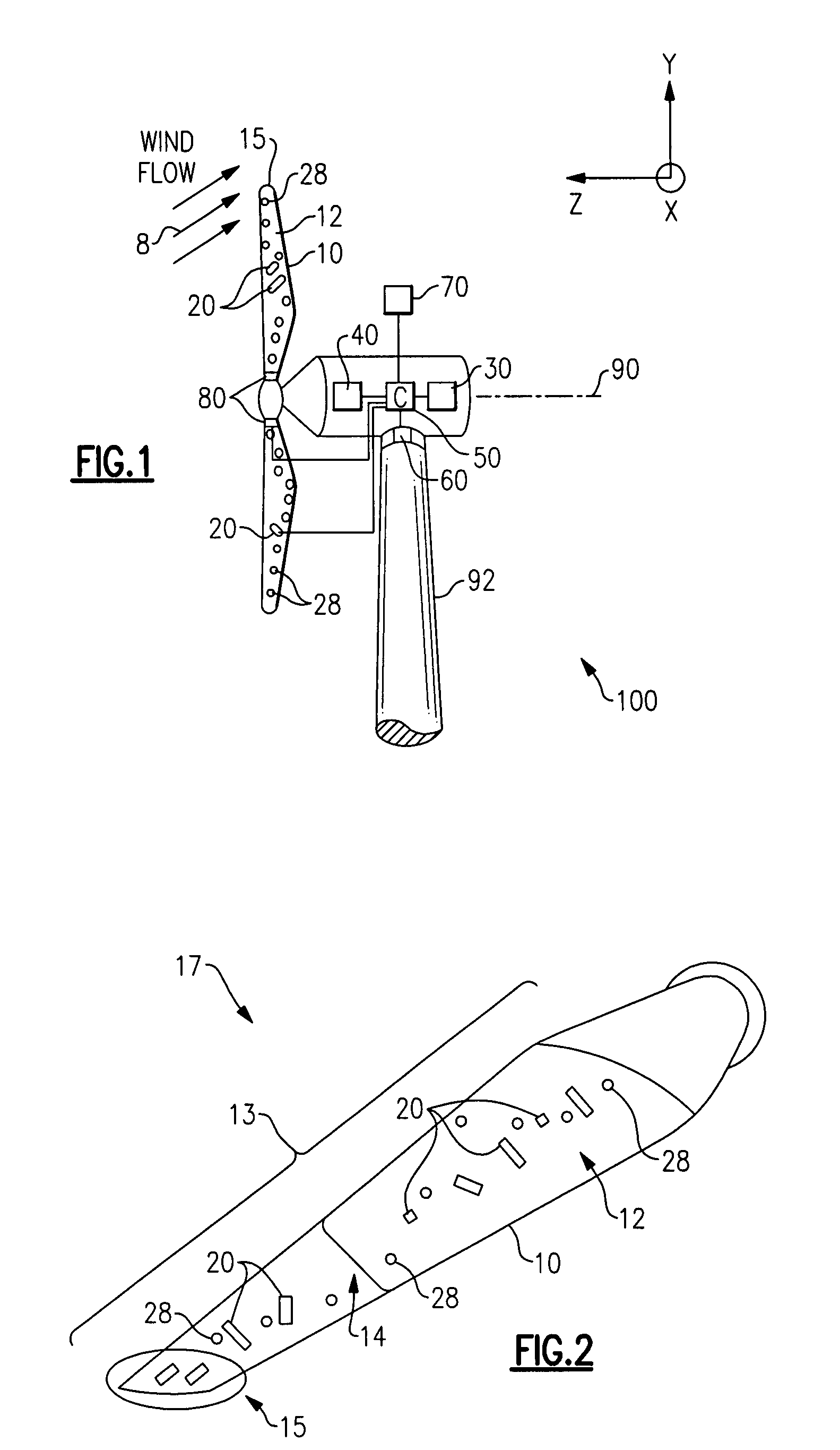
[0016]FIG. 1 illustrates a wind turbine 100 in accordance with one embodiment of the present invention. The wind turbine 100 includes a wind turbine blade 10 configured to rotate about an axis 90 upon impact of an incident wind flow, for example, a wind flow 8 as shown. It is appreciated that as used herein, the terms “a”, “an” and “the” refer to “at least one” and plural variants thereof, unless otherwise specifically mentioned or indicated by the context. The axis of rotation 90 is along the z-axis in the axes system of FIG. 1, and the plane of rotation of the blades 10 is x-y plane, the x-axis coming out of the plane of the paper. An active flow modification device 20 and a load sensor such as a fiber optic sensor 28 are further disposed on the blade 10; and the blade, active flow modification device 20 and fiber optic sensor 28 together form a wind turbine blade assembly 17 (shown in FIG. 2).

[0017]Other types of load sensors can also be employed, such as, but not limited to, uns...


PUM


Abstract

A wind turbine blade assembly includes at least one local load sensor disposed on and / or within a surface of the wind turbine blade and at least one active flow modification device disposed on and / or within a surface of the wind turbine blade and configured to alter the aerodynamics of the wind turbine blade in response to real time local load sensor measurements such that a difference between a current angle of attack and an optimum angle of attack on the wind turbine blade is substantially minimized.

Description

BACKGROUND[0001]This invention relates generally to the field of wind turbines, and more specifically to localized sensing and actuation systems to reduce the effect of angle of attack deviation (from the planned / controlled value) on power and loads in turbulent winds.[0002]Wind turbines are increasingly gaining importance in the area of renewable sources of energy generation. In recent times, wind turbine technology has been applied to large-scale power generation applications. Maximizing wind turbine performance while minimizing system loads in given wind conditions is one of the many challenges that exist in harnessing wind energy. Non-limiting examples of improved wind turbine performance parameters, which lead to minimized cost of energy, include maximized aerodynamic efficiency, maximized energy output, minimized wind turbine system loads, minimized noise, and combinations thereof. Examples of wind turbine system loads include extreme loads (operational and parked / idling) and ...

Claims


Application Information

Patent Timeline
Patent Type & Authority Applications(United States)
IPC IPC(8): F03D7/04
CPCF03D7/022F03D7/042F05B2270/32F05B2270/328F05B2270/331Y02E10/721Y02E10/723Y02E10/72
Inventor BARBU, CORNELIUGUPTA, ANURAG
Owner GENERAL ELECTRIC CO
Why Eureka
Try Eureka