Device for Stacking Synthetic Fibers to Form a Nonwoven

a technology of synthetic fibers and stacked fibers, which is applied in the direction of dough extruding machines, dough shaping, manufacturing tools, etc., can solve the problems of exhaust equipment sucking in a substantial portion of ambient air, increasing air consumption, and improving the flexibility of adjustability, so as to achieve the effect of implementing differences in heigh

Active Publication Date: 2008-12-25
ALBIS INT
View PDF8 Cites 21 Cited by
  • Summary
  • Abstract
  • Description
  • Claims
  • Application Information

AI Technical Summary

Benefits of technology

[0008]The invention is characterized in that there is a seal on the longitudinal side of the guide duct between the depositing belt and the end of the guide duct, which seal shields the depositing area from the ambience. The elasticity of the sealing lip brings about a pre-stress which firstly prevents the sealing lip from being lifted off or separated during its frictional contact with the depositing belt. Secondly, the sealing lip can advantageously compensate for unevenness on the depositing belt. It is thus possible to prevent external air from being sucked in.
[0009]In order to shield the depositing area on the depositing belt as completely as possible, the guide duct comprises, on its opposite longitudinal side, a second mobile retaining flap, which is formed by a second support and a second elastic sealing lip, which is held in frictional contact with the non-woven web stacked on the depositing belt during operation according to an advantageous refinement of the invention. It is thus possible to achieve advantageously a high sealing effect in relation to the entry of external air on that longitudinal side of the guide duct, on which the non-woven web is guided from the depositing area. The fibers are thus stacked substantially without any influences of suctioned ambient air. Additionally, the adjustability of the retaining flaps relative to the depositing belt is completely retained. For this purpose, the support with the elastic sealing lip held thereon is guided in various positions relative to the depositing belt. The adjustability of the supports and the sealing lips provides the possibility of influencing the depositing angle and the entire depositing pattern of the fibers. Thus broad or narrow depositing areas can be adjusted on the depositing belt.
[0010]The sealing lips are connected replaceably to the supports according to an advantageous refinement of the invention so as to be able to carry out the appropriate maintenance work rapidly in the case of worn out sealing lips.
[0014]The flexibility of the adjustability for depositing the fibers can be increased advantageously by holding the guide duct by means of a bracket below the take-off nozzle, the holding elements located opposite to one another in the longitudinal sides enabling a displacement and adjustment of the associated duct elements. It is thus possible to influence the depositing directly when the fibers leave the take-off nozzle.
[0020]For further improving the flexibility of the adjustability, it is possible in another preferred refinement of the invention, to change and adjust a depositing height between the take-off nozzle and the depositing belt.

Problems solved by technology

However, the disadvantage of the device disclosed is that slots are formed between the ends of the guide duct and the depositing belt.
Such slots result in the exhaust equipment sucking in a substantial portion of the ambient air together with the supplied air stream.
This results in increased air consumption and, in particular, a direct influence of the fiber depositing for forming the non-woven web.
There exists the risk of obtaining so-called drifts in the non-woven web.
However, the disadvantage of this device is that the fibers can only be stacked in a depositing area, which is kept constant.
It is not possible to change the depositing area on the depositing belt.

Method used


Image

  • Device for Stacking Synthetic Fibers to Form a Nonwoven
  • Device for Stacking Synthetic Fibers to Form a Nonwoven
  • Device for Stacking Synthetic Fibers to Form a Nonwoven

Examples


Embodiment Construction

[0030]The present invention now will be described more fully hereinafter with reference to the accompanying drawings, in which some, but not all embodiments of the invention are shown. Indeed, the present invention may be embodied in many different forms and should not be construed as limited to the embodiments set forth herein; rather, these embodiments are provided so that this disclosure will satisfy applicable legal requirements. Like numbers refer to like elements throughout.

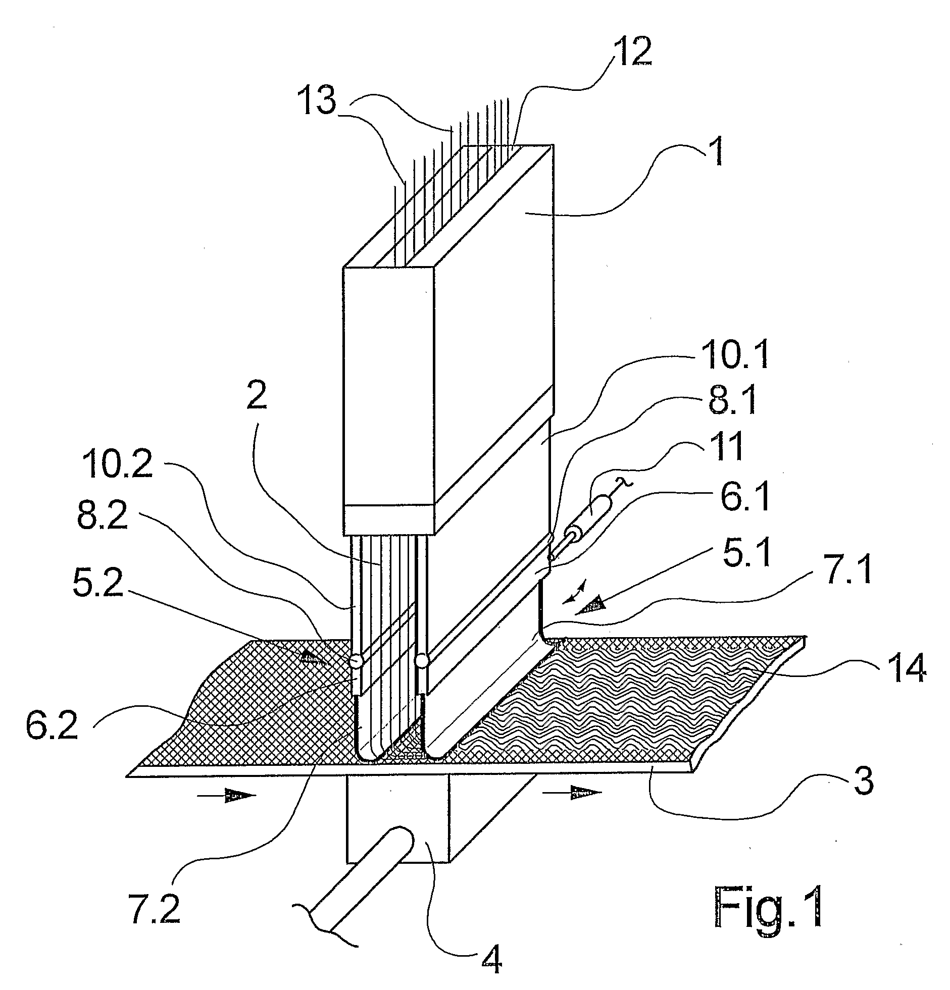
[0031]FIG. 1 schematically shows a first exemplary embodiment of the device of the invention for depositing synthetic fibers to form a non-woven web.

[0032]The exemplary embodiment shown in FIG. 1 shows a parallelepiped take-off nozzle 1 with a central fiber channel 12. A plurality of fibers 13 is guided in a row in the fiber channel 12. The fibers 13 are spun previously by means of a spinneret (not shown) from a synthetic polymer melt.

[0033]Compressed air is supplied into the take-off nozzle 1 in the fiber ...


PUM

PropertyMeasurementUnit
thicknessaaaaaaaaaa
heightaaaaaaaaaa
areaaaaaaaaaaa

Abstract

The invention relates to a device for depositing synthetic fibers to form a non-woven web. The fibers are transported through a take-off nozzle by means of an air stream in the direction of a depositing belt. The device is provided with a guide duct for guiding fibers from the take-off nozzle to the depositing belt, said duct having a mobile retaining flap on one end of a longitudinal side that faces the depositing belt. To obtain a depositing area on the depositing belt that is separate from the environment as the position of the retaining flap is modified, the retaining flap is formed by a support and an elastic sealing lip, which is held in frictional contact with the depositing belt.

Description

BACKGROUND OF THE INVENTION[0001]The invention relates to a device for depositing synthetic fibers to form a non-woven web. In the production of spun-bond non-woven webs, freshly spun synthetic fibers are usually drawn off by means of a take-off nozzle of a spinneret and conveyed for being stacked on a depositing belt. The processes of guiding and conveying the fibers are brought about by means of an air stream of the take-off nozzle, which air stream is absorbed and discharged by exhaust equipment disposed below the depositing belt. The fibers accumulating on the surface of the depositing belt result in a non-woven web, which is conveyed continuously by the depositing belt. The formation of the non-woven web depends on the impingement of the fibers on the depositing belt and the belt speed. A change in the airflow can influence the impingement of the fibers, in particular.[0002]Thus, for example, DE 37 40 893 A1 discloses a device for depositing synthetic fibers to form a non-woven...

Claims


Application Information

Patent Timeline
Patent Type & Authority Applications(United States)
IPC IPC(8): D04H3/03B29C48/90D04H3/16
CPCD04H3/03D04H3/16
Inventor BOSCOLO, GALLIANOHEESCH, HANS-HOLGER
Owner ALBIS INT
Why Eureka
Try Eureka