Stent With Improved Mechanical Properties

Inactive Publication Date: 2008-12-25
MEDTRONIC VASCULAR INC
View PDF19 Cites 43 Cited by
  • Summary
  • Abstract
  • Description
  • Claims
  • Application Information

AI Technical Summary

Benefits of technology

[0010]It is an aspect of the present invention to provide a stent having improved

Problems solved by technology

Dilation of the occlusion, however, can form flaps, fissures or dissections, which may threaten, re-closure of the dilated vessel.
However, by varying the amplitudes of the waves, the stent may exhibit non-uniform behavior as the stent is crimped onto a balloon and/or expanded at the deployment site, due to different moments and bending force

Method used


Image

  • Stent With Improved Mechanical Properties
  • Stent With Improved Mechanical Properties
  • Stent With Improved Mechanical Properties

Examples


Example

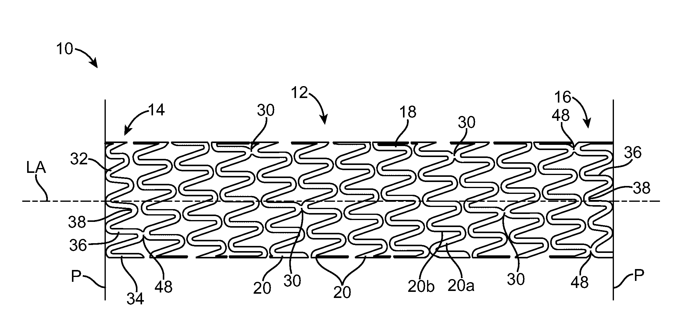
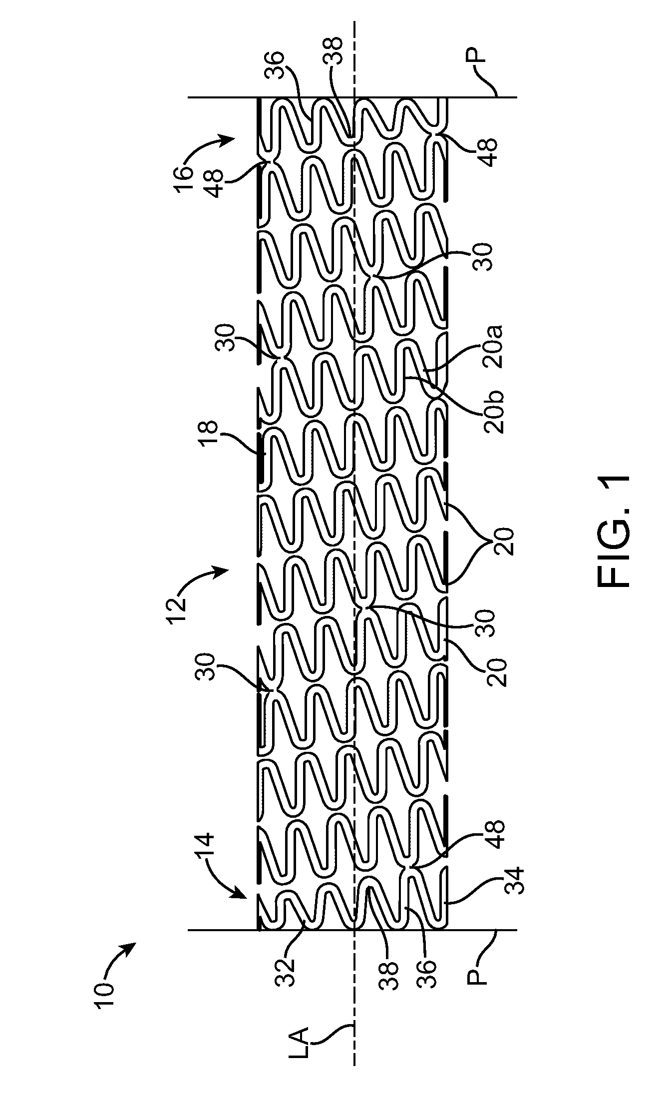
[0022]FIG. 1 illustrates a stent 10 according to an embodiment of the present invention. As illustrated, the stent 10 includes a central portion 12, a first end segment 14 that is connected to one end of the central portion 12, and a second end segment 16 that is connected to an opposite end of the central portion 12 as the first end segment 14. The stent 10 is generally cylindrical in shape and has a longitudinal axis LA extending through the center of the stent 10, as shown in FIG. 1.

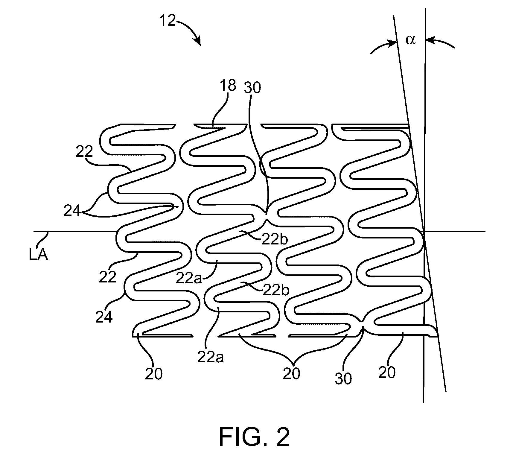
[0023]The central portion 12 of the stent, a portion of which is shown in greater detail in FIG. 2, is defined by a continuous waveform 18 that is wrapped around the longitudinal axis LA at a predetermined pitch a to form a helix having a plurality of helical turns 20. The continuous waveform 18 includes a plurality of struts 22 and a plurality of crowns 24 (or turns) that connect adjacent struts to each other. As illustrated, the struts 22 are substantially straight, although it is contemplated that ...


PUM


Abstract

A stent includes a central portion having a first waveform. The first waveform is wrapped around a longitudinal axis of the stent at a pitch to define a plurality of helical turns. The stent also includes an end segment connected to one end of the central portion. The end segment has a second waveform that includes a plurality of struts and a plurality of crowns. Each of the plurality of struts has a different length so that peaks of the crowns that define an end of the stent lie within a plane that is substantially perpendicular to the longitudinal axis. Cross-sectional areas of the struts having different lengths vary so that the struts move substantially uniformly during radial contraction and/or radial expansion of the stent.

Description

RELATED APPLICATIONS[0001]This application is a Continuation-in-Part of U.S. patent application Ser. No. 11 / 767,308 filed Jun. 22, 2007.BACKGROUND OF THE INVENTION[0002]1. Field of the Invention[0003]The present invention generally relates to stents. More particularly, the present invention relates to helical coil stents having improved mechanical properties.[0004]2. Description of Related Art[0005]Percutaneous transluminal angioplasty (PTCA) is used to open coronary arteries, which have been occluded by a build-up of cholesterol fats or atherosclerotic plaque. Typically, a guide catheter is inserted into a major artery in the groin and is passed to the heart, providing a conduit to the ostia of the coronary arteries from outside the body. A balloon catheter and guidewire are advanced through the guiding catheter and steered through the coronary vasculature to the site of therapy. The balloon at the distal end of the catheter is inflated, causing the site of the stenosis to widen. D...

Claims


Application Information

Patent Timeline
IPC IPC(8): A61F2/06
CPCA61F2/88A61F2/915A61F2002/91508A61F2002/91558A61F2250/0036A61F2220/0058
Inventor KRIVORUCHKO, MICHAELBIRDSALL, MATTHEWPELLEGRINI, GIANFRANCOGOSHGARIAN, JUSTINALLEN, JEFFREY
Owner MEDTRONIC VASCULAR INC
Why Eureka
Try Eureka