Apparatus for the fibre-sorting or fibre-selection of a fibre bundle comprising textile fibres, especially for combing

a technology of textile fibre bundles and apparatuses, which is applied in the direction of textiles and paper, carding machines, fibre treatment, etc., can solve the problems of high demands on the framework of the machine as well as the base, the back and forth swinging movement of the nipper assembly giving rise to very substantial vibration, and the discontinuous mode of operation. , to achieve the effect of improving the combed sliver and substantially increasing the amount of hours produced

Inactive Publication Date: 2009-01-01
TRUETZSCHLER GMBH & CO KG
View PDF54 Cites 30 Cited by
  • Summary
  • Abstract
  • Description
  • Claims
  • Application Information

AI Technical Summary

Benefits of technology

[0012]It is an aim of the invention is to provide an apparatus of the kind described at the beginning which avoids or mitigates the mentioned disadvantages and which in a simple way, in particular, enables the amount produced per hour (productivity) to be substantially increased and an improved combed sliver to be obtained.
[0018]By implementing the functions of clamping and moving the fibre bundles to be combed-out on at least two rotating rollers, high operating speeds (nip rates) are achievable—unlike the known apparatus—without large mass accelerations and reversing movements. In particular, the mode of operation is continuous. When two high-speed rollers are used, a very substantial increase in hourly production rate (productivity) is achievable which had previously not been considered possible in technical circles. A further advantage is that the rotary rotational movement of the rollers with the plurality of clamping devices leads to an unusually rapid supply of a plurality of fibre bundles per unit of time to the first roller and to the second roller. In particular the high rotational speed of the rollers allows production to be substantially increased.
[0020]The fibre bundles are—unlike the known apparatus—held by a plurality of clamping devices and transported under rotation. The clamping point at the particular clamping devices therefore remains constant until the fibre bundles are transferred to the first or second roller respectively. A relative movement between clamping device and fibre bundle does not begin until after the fibre bundle has been gripped by the first or second roller respectively and in addition clamping has been terminated. Because a plurality of clamping devices is available for the fibre bundles, in an especially advantageous manner fibre bundles can be supplied to the first and second roller respectively one after the other and in quick succession, without undesirable time delays resulting from just a single supply device. A particular advantage is that the supplied fibre bundles on the first roller (turning rotor) are continuously transported. The speed of the fibre bundle and of the co-operating clamping elements is the same. The clamping elements close and open during the movement in the direction of the transported fibre material. The at least two rotating rollers comprise at least one first roller (the or each first roller preferably being a turning rotor) and at least one second roller (the or each second roller preferably being a combing rotor). The at least one second roller (that is, preferably a combing rotor) is arranged downstream of the at least one first roller (that is, preferably a turning rotor). With the apparatus according to the invention, a substantially increased productivity is achieved. A further particular advantage is that at high and maximum operating speeds of the rotor combing machine, the oscillating movement of a clamping jaw, for example, of the bottom nipper, is implemented in such a way that the transfer point (clamping point) is substantially maintained, for example, in the region of the in-feed despite the rotary movement of the rotor. The period of time available for clamping the fibre tuft is consequently extended. This enables the acceleration of a clamping jaw (upper nipper) to be reduced or the operating frequency to be increased.
[0028]In some embodiments a firm or resilient counter-layer is arranged, for example, on the lower nipper. If desired, the clamping points may be provided with contours improving clamping. In some embodiments, plastics material or rubber elements are used on the upper nipper and / or the lower nipper or counter-layer to improve the friction pairing.

Problems solved by technology

A disadvantage of that known combing method is, in particular, the discontinuous mode of operation, in which large masses have to be accelerated and decelerated during the operating cycle.
The back and forth swinging movement of the nipper assembly gives rise to very substantial vibration, especially in the case of high nip rates, which on the one hand requires the drive elements and bearing elements to be of suitably stable construction and on the other hand places high demands on the framework of the machine as well as on the base on which the machine is mounted.
In the case of the 450 nips per minute usually required, the large masses being moved result in a high level of dynamic agitation of the entire combing machine which limits its operating speed and productivity.
Furthermore, a problem of conventional combing machines is that when the combed fibres are removed by the counter-rotating take-off rollers, up to 50% of the fibre length has not been cleaned by the circular comb, because during the combing process, that is to say when the combing segment passes, the fibres were clamped between the jaws of the nipper arrangement or were located behind the jaws, seen in the transport direction.
Such an arrangement is disadvantageous because, in particular, the nipper apparatus has to perform a variety of very large movements with greater or lesser degrees of acceleration.
The operating speed is thus considerably limited, a large amount of noise is generated and the inertial forces that arise result in above-average wear.
A further crucial disadvantage is that the free end of the fibre tuft that has just been combed also has to be moved at relatively high speed, with its free fibre tips to the front, over large distances and placed in an exactly defined position onto the returned end of the combed sliver.
In any case, however, losses of quality are observed in the combed sliver.
A further disadvantage of the known apparatus is that uncontrolled fold-formation occurs between the detaching roller pair and the take-off rollers as a result of the pilgrim-step motion of the detaching rollers, which additionally results in disruption of the combing process.
High nip rates result in high acceleration.
The known flat combing machine has reached a performance limit with its nip rates, which prevents productivity from being increased.
Furthermore, the discontinuous mode of operation causes vibration in the entire machine which generates dynamic alternating stresses.
Disadvantages of that combing machine are especially the large amount of equipment required and the low hourly production rate.
A particular problem is the discontinuous mode of operation of the combing heads.
Additional disadvantages result from large mass accelerations and reversing movements, with the result that high operating speeds are not possible.
Finally, the considerable amount of machine vibration results in irregularities in the deposition of the combed sliver.
Moreover, the ecartement, that is to say the distance between the nipper lip of the lower nipper plate and the clamping point of the detaching cylinder, is structurally and spatially limited.

Method used


Image

  • Apparatus for the fibre-sorting or fibre-selection of a fibre bundle comprising textile fibres, especially for combing
  • Apparatus for the fibre-sorting or fibre-selection of a fibre bundle comprising textile fibres, especially for combing
  • Apparatus for the fibre-sorting or fibre-selection of a fibre bundle comprising textile fibres, especially for combing

Examples


Embodiment Construction

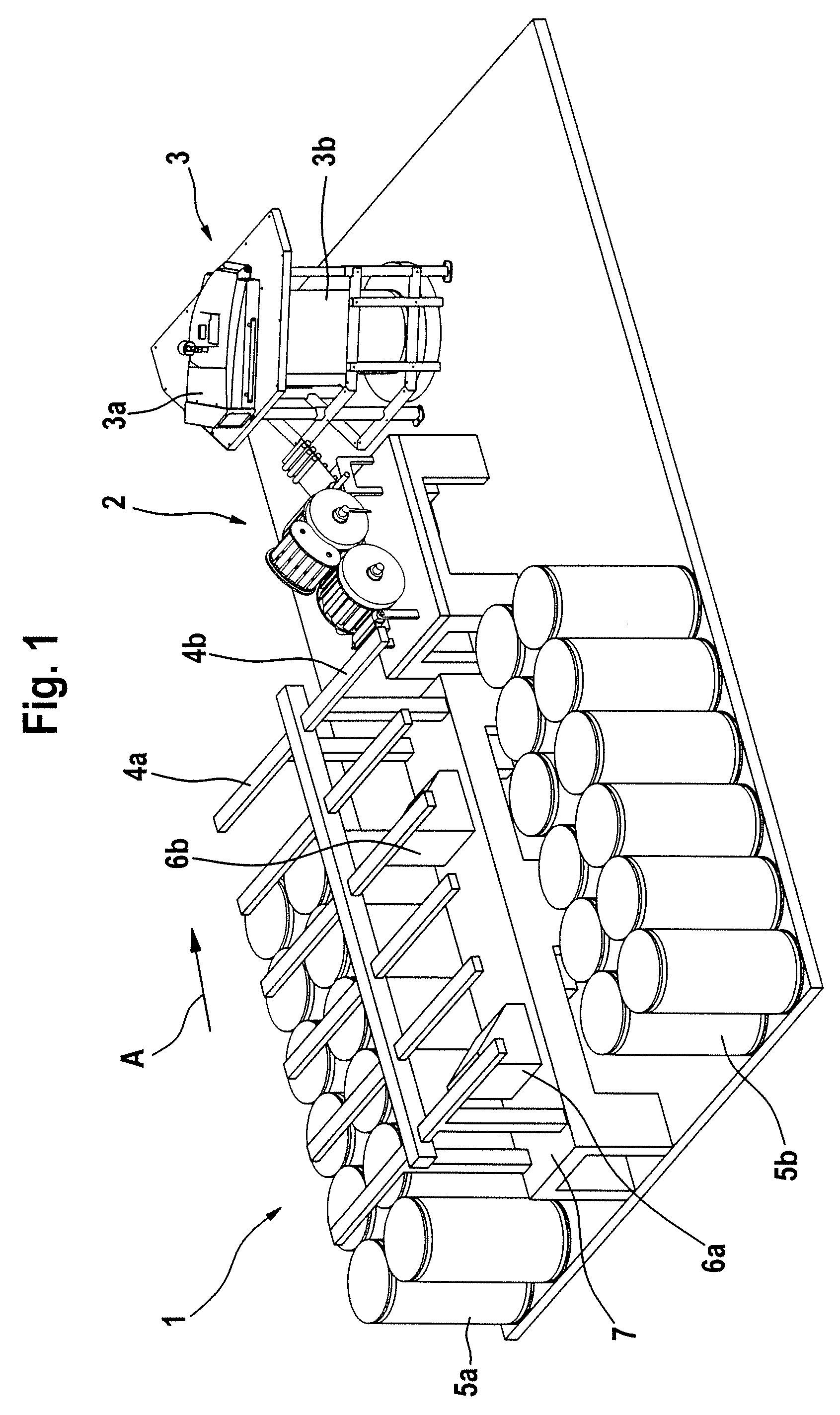
[0050]With reference to FIG. 1, a combing preparation machine 1 has a sliver-fed and lap-delivering spinning room machine and two feed tables 4a, 4b (creels) arranged parallel to one another, there being arranged below each of the feed tables 4a, 4b two rows of cans 5a, 5b containing fibre slivers (not shown). The fibre slivers withdrawn from the cans 5a, 5b pass, after a change of direction, into two drafting systems 6a, 6b of the combing preparation machine 1, which are arranged one after the other. From the drafting system 6a, the fibre sliver web that has been formed is guided over the web table 7 and, at the outlet of the drafting system 6b, laid one over the other and brought together with the fibre sliver web produced therein. By means of the drafting systems 6a and 6b, in each case a plurality of fibre slivers are combined to form a lap and drafted together. A plurality of drafted laps (two laps in the example shown) are doubled by being placed one on top of the other. The l...


PUM

PropertyMeasurementUnit
clamping forceaaaaaaaaaa
diameteraaaaaaaaaa
distanceaaaaaaaaaa

Abstract

In an apparatus for the fibre-sorting or fibre-selection of a fibre bundle comprising textile fibres, especially for combing, which is suppled by a supply device to a fibre-sorting device, especially a combing device, having clamping devices which clamp the fibre bundle at a distance from its free end, which is combed to remove non-clamped constituents, the clamping devices each comprise two clamping jaws. To increase productivity and to enable an improved combed sliver to be obtained, downstream of the supply device there are arranged at least two rotatably mounted rollers rotating rapidly without interruption, the clamping devices being spaced apart in the region of the periphery of the rollers, and the clamping jaws of the each clamping device are arranged to be movable in relation to one another and separately drivable.

Description

CROSS REFERENCE TO RELATED APPLICATIONS[0001]This application claims priority from German Utility Model No. 20 2007 010 686.6 dated Jun. 29, 2008 and German Patent Application No. 10 2008 014 173.9 dated Mar. 14, 2008, the entire disclosure of each of which is incorporated herein by reference.BACKGROUND OF THE INVENTION[0002]The invention relates to an apparatus for the fibre-sorting or selection of a fibre bundle comprising textile fibres, especially for combing, which is supplied by means of supply means to a fibre-sorting device, especially to a combing device, in which clamping devices are provided, which clamp the fibre bundle at a distance from its free end and mechanical means are present which generate a combing action from the clamping site to the free end of the fibre bundle in order to loosen and remove non-clamped constituents, such as, for example, short fibres, neps, dust and the like from the free end, wherein for removal of the combed fibre material at least one take...

Claims


Application Information

Patent Timeline
Patent Type & Authority Applications(United States)
IPC IPC(8): D01G19/00
CPCD01G15/40D01G19/16D01G19/08
Inventor SAEGER, NICOLEBOSSMANN, JOHANNESSCHMITZ, THOMAS
Owner TRUETZSCHLER GMBH & CO KG
Why Eureka
Try Eureka