Window Lift System and Method for Fitting a Window Pane

a technology for lifting systems and windows, applied in the field of windows and lift systems, can solve the problems of unfavorable rattling, difficult fitting of windows, and difficulty in fitting windows, and achieve the effects of low linear extensibility, high tensile stability, and good flexibility

Inactive Publication Date: 2009-01-01
FAURECIA INNENRAUM SYST
View PDF14 Cites 9 Cited by
  • Summary
  • Abstract
  • Description
  • Claims
  • Application Information

AI Technical Summary

Benefits of technology

[0016]In typical embodiments of the invention, the pulling device will have a cable pull or a chain, so that the upwardly pulling end and the downwardly pulling end of the pulling device each form one end of this cable pull or chain. A wire or plastic cable suggests itself for example as the cable pull, with a view to as high tensile stability as possible, low linear extensibility and good flexibility. Possible, too, are those embodiments in which two independent pulling devices, for example cable pulls or chains, are provided each for one end fastened to the catch. The pulling device of a window lift system of the described art typically has furthermore deflections formed for example by rollers and / or sliding blocks, as well as a drive system provided e.g. by a crank drive or an electric motor.

Problems solved by technology

The same torque transferred via the catch to the window pane once the window pane is fitted, however, results in the catch being pulled, before the fitting of the window pane, into an oblique position which makes fitting the window pane extraordinarily difficult, especially connecting the window pane to the catch.
Fitting the window pane is also made more difficult in that the catch which previously was typically only held by the two ends has at least one degree of rotational freedom, and can thus rotate freely at least about one axis.
This can furthermore lead to undesired rattling when the corresponding door or side panel module which contains a corresponding window lift system is transported.

Method used


Image

  • Window Lift System and Method for Fitting a Window Pane
  • Window Lift System and Method for Fitting a Window Pane
  • Window Lift System and Method for Fitting a Window Pane

Examples


Embodiment Construction

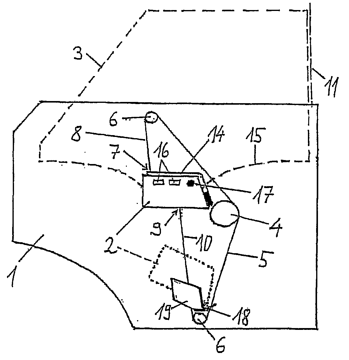
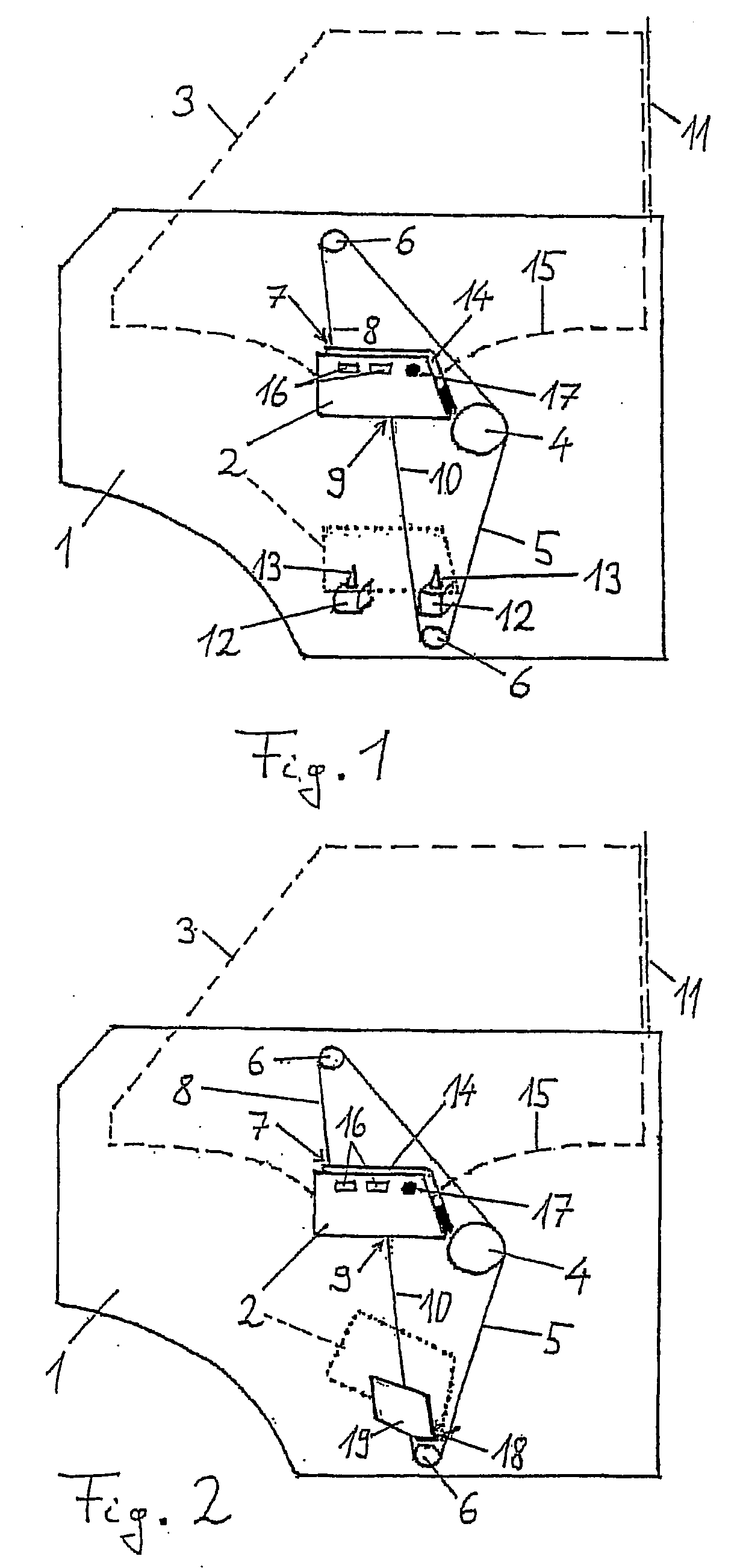
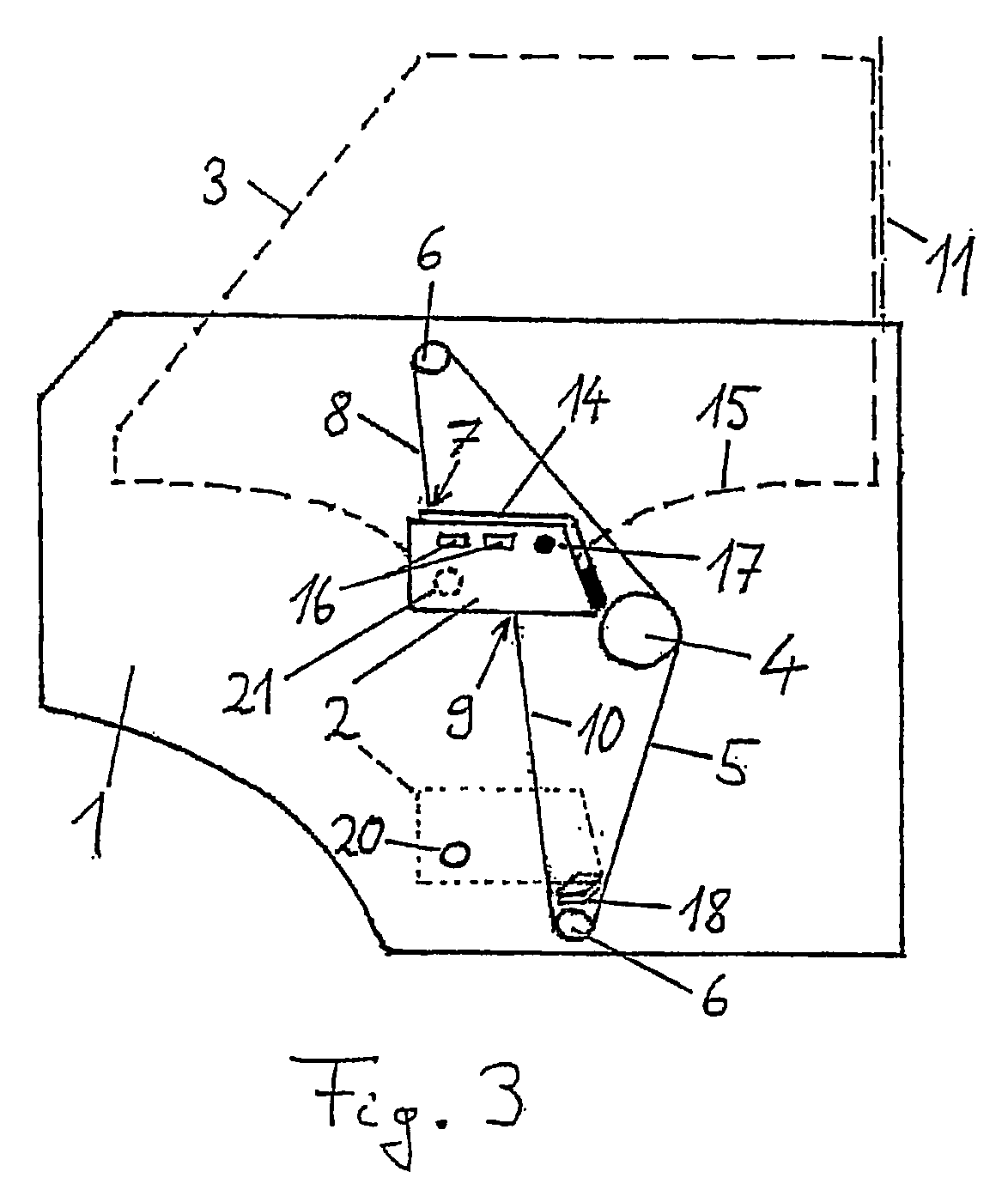
[0028]Thus in FIG. 1 a door module is illustrated which is intended to be installed in the left-hand front side door of an automotive vehicle. This door module has a panel part 1 formed from an injection-moulded fibre-reinforced plastic on which a window lift system is arranged and which at the same time serves as a partition between a wet region and a dry region, covered by the panel part in the figure, of the corresponding side door. The window lift system has a catch 2, which can be moved up and down by a pulling device, for a window pane 3 indicated with a broken line in the figure. Recognisable in the figure as constituent parts of the pulling device are a drum, which may be driven by a crank drive, not shown, or an electric motor, a traction cable 5 wound over this drum 4 and therefore mobile, as well as two deflection elements for the traction cable 5 in the form of rollers. In other embodiments of the invention, the deflection elements 6 can also be in the form of sliding bl...


PUM


Abstract

A window lift system, especially for the side window of a motor vehicle, includes (i) a pulling device and (ii) a catch for a window pane, which can be moved up and down using the pulling device. The catch has a first fastening point for an upward pulling end of the pulling device and a second fastening point for a downward pulling end of the pulling device, which point is horizontally off-set from the first fastening point in the window pane plane when the window pane is fitted. The window lift system also includes (iii) an arrangement positioning and fixating the catch in terms of at least three degrees of freedom so that the catch can be maintained in a position that is defined in terms of the degrees of freedom even when the window pane is not yet fitted.

Description

FIELD OF INVENTION[0001]The present invention relates to a window lift system, especially a window lift system for a side window of an automotive vehicle, comprising a catch for a window pane which can be moved up and down by a pulling device, in accordance with the preamble of the main claim. The present invention relates furthermore to a door or side panel module which contains such a window lift system, as well as to a method for fitting a window pane in such a window lift system.BACKGROUND INFORMATION[0002]In a window lift system of this type, the catch has a first fastening point for an upwardly pulling end of the pulling device and a second fastening point for a downwardly pulling end of the pulling device, this second point being horizontally offset to the first fastening point in the window pane plane once the window pane is fitted. Such a window lift system is known from the publication DE 690 27 127 T2.[0003]Window lift systems of this type are of particular interest when ...

Claims


Application Information

Patent Timeline
Patent Type & Authority Applications(United States)
IPC IPC(8): E05F11/48E05F11/38
CPCE05F11/382E05F11/385E05F11/486E05Y2201/218E05Y2900/55E05Y2201/654E05Y2800/692E05Y2800/696E05Y2201/64E05F2011/387B60J1/17B60J5/04E05F11/38E05F11/48
Inventor ECKHARDT, BERNHARDSIELHORST, BERNHARDSCHLIWA, ENRICOKOLLNER, HARALD
Owner FAURECIA INNENRAUM SYST
Why Eureka
Try Eureka