Piston-cylinder unit

a technology of piston cylinder and piston cylinder, which is applied in the direction of shock absorbers, machines/engines, transportation and packaging, etc., can solve the problems of high-frequency excitation, uncomfortable sensation, transmission of vibration and noise into the passenger compartment, etc., and achieve the effect of increasing the driving comfor

Inactive Publication Date: 2009-01-01
ZF FRIEDRICHSHAFEN AG
View PDF5 Cites 5 Cited by
  • Summary
  • Abstract
  • Description
  • Claims
  • Application Information

AI Technical Summary

Benefits of technology

[0008]The advantage of the invention is that the fastening elements, when used as level-control elements, can satisfactorily support the vehicle body as well as any extra weight loaded onto the vehicle, but at the same time an optimum of driving comfort and noise isolation in the vehicle is present in the high-frequency, small-amplitude range of the excitations caused by the road surface. When the piston-cylinder unit is excited at high frequency with small amplitudes, most of the force is absorbed by the fastening element, at least one of which is provided, in that relative axial movement takes place between the fastening element and the piston rod or a fastening element on the working cylinder or on the container tube. When the excitations are no longer in the short-stroke, usually high-frequency range, that is, if the excitation is now of the low-frequency, large-amplitude type, the fastening element arrives in its end position with respect to its adjacent component, namely, the piston rod or the working cylinder, and then the pressure required to produce the damping force can be built up at the damping valves of the piston. In this way, both discontinuities in the damping force and noise, which is transmitted to the body of the vehicle, are avoided, and thus driving comfort can be increased.
[0009]According to another feature, the effective pressure-actuated end surface of the piston rod or the effective pressure-actuated end surface of the journal and the effective pressure-actuated cross-sectional area of the piston rod inside the piston-cylinder unit are all of equal size. The advantage here is that the pressure-equalized piston rod is isolated from the fastening bearing, and the elastic piston rod connection is not called upon to provide any bearing force at all. The bearing force is generated exclusively by the damping medium in the hollow piston rod, which is under the system pressure, where the pressure of the damping medium acts on the area of the bottom region of the chamber, which is of the same size as the cross-sectional area of the piston rod.
[0010]According to still another feature, the effective pressure-actuated end surface of the piston rod or the effective pressure-actuated end surface of the journal and the effective pressure-actuated cross-sectional area of the piston rod inside the piston-cylinder unit are of different sizes, depending on the required pretension of the piston rod in the inward-travel or outward-travel direction of the piston rod.
[0011]According to one embodiment, at least one elastic element is provided as a stop between the fastening element and the piston rod and / or the working cylinder.
[0012]According to another embodiment, a chamber, serving a damping purpose, is formed between the cylindrical bore and the end surface of the piston rod and / or the journal. It is advantageous here for the chamber to be filled with the incompressible medium present in the piston-cylinder unit and for the chamber to be connected to one of the working spaces of the working cylinder by a flow connection.
[0013]According to still another embodiment, the chamber is sealed off against the atmosphere by a seal.

Problems solved by technology

These fastening devices suffer from the disadvantage that they produce an uncomfortable sensation when subjected to high-frequency excitation by the road surface, especially at small amplitudes.
One of the reasons for this is that the rubber fastening parts of the vibration damper at the vehicle body or at the wheel suspension become hard and thus transmit vibrations and noise into the passenger compartment.
In addition, because of the high natural frequency and the short-stroke movement of the piston, the alternating action of the damping and check valves of the damping piston becomes progressively worse, so that again an uncomfortable stiffening of the piston-cylinder unit is present.

Method used


Image

  • Piston-cylinder unit
  • Piston-cylinder unit
  • Piston-cylinder unit

Examples


Embodiment Construction

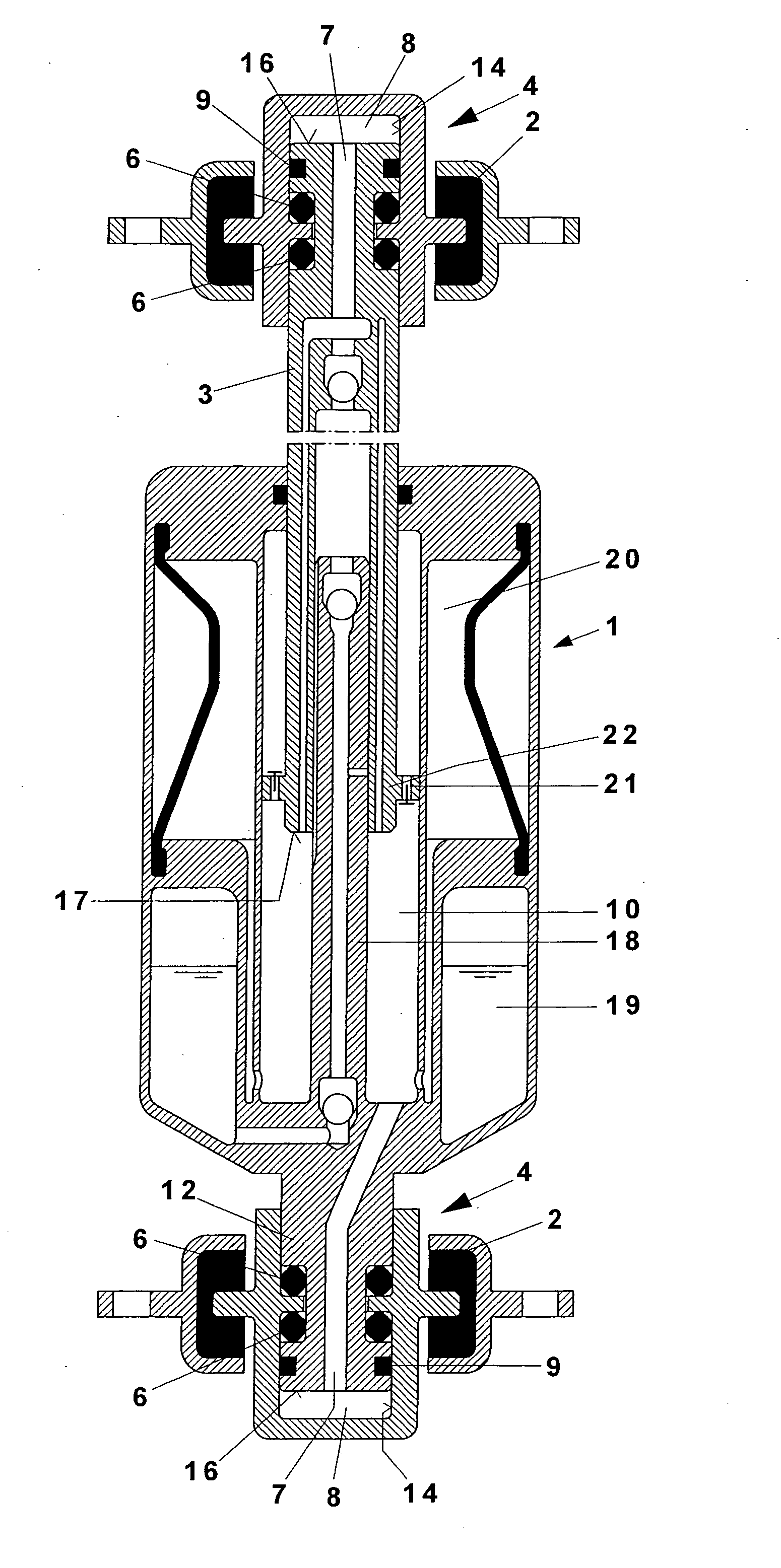
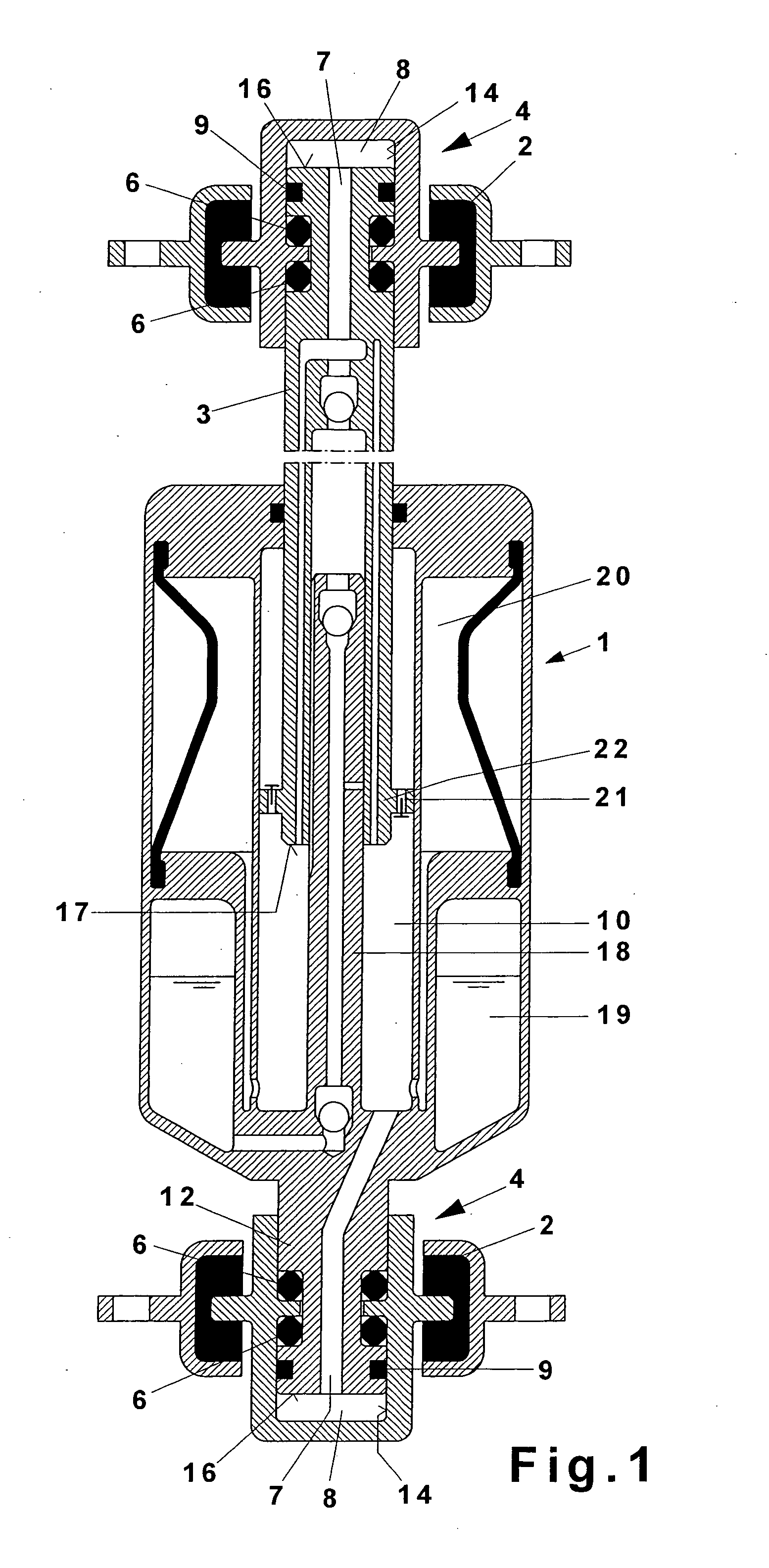
[0026]A piston rod 3 of a piston-cylinder unit 1 shown in FIG. 1 includes a fastening element 4 that includes a rubber-metal part 2 so that it can be fastened to the body of a vehicle. As shown in the lower area, the cylinder of the piston-cylinder unit 1 also includes a fastening element 4 that includes another rubber-metal part 2 so that it can be connected to the axle of the motor vehicle.

[0027]Through the design of the piston-cylinder unit 1 as a hydropneumatic level control device, the piston rod 3 is brought to a predetermined level by the internal pressure of the unit as a function of load.

[0028]Each upper fastening element 4 in FIG. 1 defines a cylindrical bore 14 in which the piston rod 3 is received. The fastening element 4 is connected to the piston rod 3, in that the piston rod 3 cooperates with a radial projection of the fastening element 4 by way of elastic elements 6. The lower fastening element 4 is similarly connected to a journal 12 of the cylinder.

[0029]The fasten...


PUM


Abstract

A piston-cylinder unit configured to provide a level adjustment function based on internal pressure includes a working cylinder, a piston rod, a working piston mounted on the piston rod, and fastening elements coupled to the piston rod and the working cylinder. Each fastening element is configured to attach to a chassis or a vehicle body. One of the fastening elements is mountable with freedom of axial movement relative to the piston rod or the working cylinder and includes a cylindrical bore and a chamber disposed between the cylindrical bore and an end surface of the piston rod or a journal of the working cylinder. The end surface of the piston rod or the journal includes a first effective pressure-actuated cross-sectional area approximately the same as a second effective pressure-actuated cross-sectional area of the piston rod. The first and the second cross-sectional areas are actuated by system pressure.

Description

BACKGROUND OF THE INVENTION[0001]1. Field of the Invention[0002]The invention relates generally piston-cylinders, and more particularly to a piston-cylinder unit that includes a fastening element that easily supports any extra weight loaded onto the vehicle and simultaneously isolates the vehicle body from high-frequency, short-stroke road excitations without any significant reduction in the damping effect at longer strokes.[0003]2. Description of the Related Art[0004]Piston-cylinder units are known, for example, from U.S. Pat. No. 6,202,993 and GB 2 144 584, where the piston rod of a piston-cylinder unit is attached to the vehicle body by way of a bearing. These bearings have elastic rubber elements to absorb vibrations. When bearing eyes are used, elastic rubber elements are also usually inserted between the eye and the vehicle body. These fastening devices suffer from the disadvantage that they produce an uncomfortable sensation when subjected to high-frequency excitation by the ...

Claims


Application Information

Patent Timeline
Patent Type & Authority Applications(United States)
IPC IPC(8): F16J3/06
CPCB60G13/001B60G13/08B60G15/068B60G15/07B60G2202/24F16F9/56B60G2204/129B60G2500/30F16F9/063F16F9/54B60G2204/128F16F9/32F16F9/50
Inventor SCHMITZ, KLAUSBECK, HUBERT
Owner ZF FRIEDRICHSHAFEN AG
Why Eureka
Try Eureka