Internal combustion engine flow regulating valve

a technology of internal combustion engine and flow regulating valve, which is applied in the direction of functional valve types, machines/engines, liquid fuel feeders, etc., can solve problems such as adverse effects on engine performan

Active Publication Date: 2009-01-01
DEERE & CO
View PDF14 Cites 6 Cited by
  • Summary
  • Abstract
  • Description
  • Claims
  • Application Information

AI Technical Summary

Problems solved by technology

Under some conditions, after shut down of the engine, air can enter into the system so that it is possible to have fuel / air or air entering the injection chamber which has an adverse affect on engine performance.

Method used


Image

  • Internal combustion engine flow regulating valve
  • Internal combustion engine flow regulating valve
  • Internal combustion engine flow regulating valve

Examples


Embodiment Construction

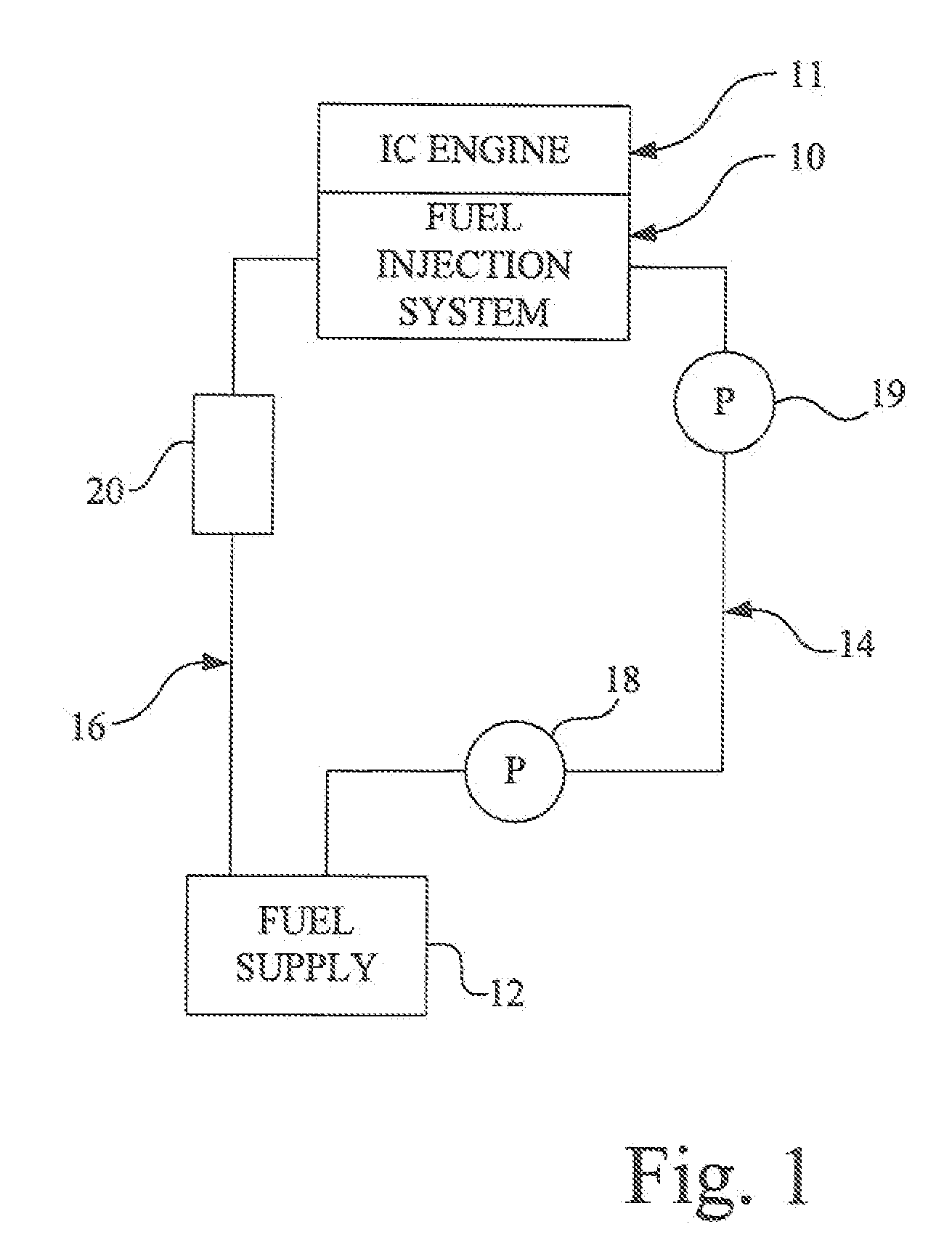
[0013]FIG. 1 shows an internal combustion engine 11 of the diesel type. Engine 11 has a fuel injection system 10 supplied with fuel from an appropriate fuel supply 12 such as a tank by way of a supply line or conduit 14 A priming pump 18 and transfer pump 19 are connected in series in supply conduit 14 to deliver fuel to the fuel injection system 10. A return line or conduit 16 connects excess fuel that has not been consumed by the engine 11 to the fuel supply 12 to complete the loop.

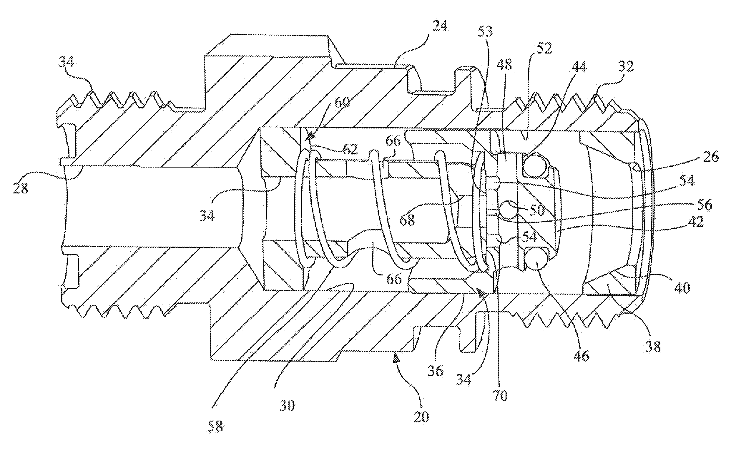
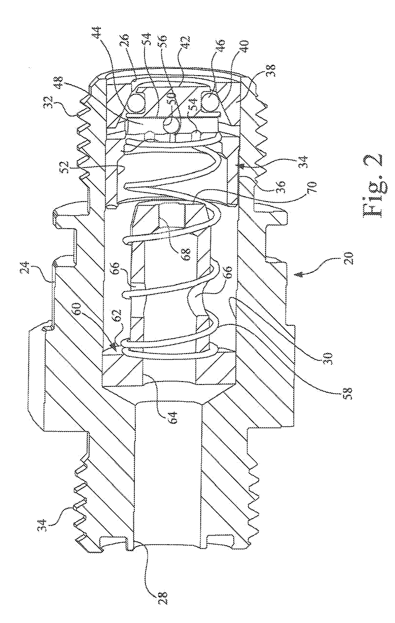
[0014]A flow regulating valve 20 is interposed in conduit 16 between the fuel injection system 10 and the fuel supply 12. Although the priming pump 18 is shown away from the fuel supply 12, it should be apparent to those skilled in the art that the pump may be in one of a number of positions.

[0015]The fuel injection system 10 may be one of a number of fuel injection systems adaptable for supplying predetermined fuel charges at a predetermined time to the combustion chamber of engine 11. For purpose of i...


PUM


Abstract

A flow regulating valve for a diesel engine in which a unitary valve element has three positions for controlling flow from a unit injector fuel injection system in response to valve inlet pressure. The valve has a first position wherein flow is blocked below about 10 psi, a second position between about 10 psi and 20 psi wherein flow is substantially unrestricted, and a third position above about 20 psi wherein flow is restricted to minimize return flow to a fuel supply and minimize fuel cooling requirements.

Description

FIELD OF THE INVENTION[0001]The invention relates to internal combustion engines and more particularly to flow regulating valves for such engines.BACKGROUND OF THE INVENTION[0002]Internal combustion engines of the diesel type are an essential part of the automotive and agriculture industries. The fundamental diesel process depends upon the heat of compression to ignite an air fuel mixture where fuel has been injected at or near top dead center during the compression stroke of the engine. Over the years, a wide variety of systems have been proposed and adopted to achieve the end of a predetermined quantity of fuel under high pressure at a predetermined time in the engine cycle to achieve the necessary performance and emission goals for the diesel engine. These fuel systems include high pressure common rail systems (HPCR), unit injectors, distributor systems, and multiple unit injector pump systems. One of the common requirements of all such systems is the ability to have a solid colu...

Claims


Application Information

Patent Timeline
Patent Type & Authority Applications(United States)
IPC IPC(8): F02M37/00
CPCF02M37/0023F02M57/023F02M37/0052Y10T137/7866
Inventor SULLIVAN, MICHAEL BRIAN
Owner DEERE & CO
Why Eureka
Try Eureka