Photovoltaic Device Characterization Apparatus

a photovoltaic device and characterization technology, applied in photovoltaic monitoring, climate sustainability, sustainable buildings, etc., can solve the problems of inability to obtain the prescribed output of certain solar cells, inability to achieve the prescribed output, and difficulty in determining whether the generated output of the photovoltaic device is corr

Inactive Publication Date: 2009-01-01
EKO INSTR
View PDF3 Cites 31 Cited by
  • Summary
  • Abstract
  • Description
  • Claims
  • Application Information

AI Technical Summary

Benefits of technology

[0012]It is thereby possible to estimate the failure with greater accuracy.
[0014]Since the conversion to the reference condition can be made by giving consideration to the error caused by the installation environment of the photovoltaic device, it is thereby possible to estimate the failure with greater accuracy.
[0016]It is thereby possible to estimate the failure with greater accuracy.
[0018]As a result of adopting the foregoing method, a simple and highly reliable comparison can be realized.
[0020]It is thereby possible to detect an abnormality such as the reverse connection of the photovoltaic device before measuring the current and prevent the characterization apparatus from becoming damaged.

Problems solved by technology

In recent years, with global environmental problems attracting attention, photovoltaic systems using solar energy, which is known to be inexhaustible and clean energy, are becoming popular.
For example, among the individual solar cells configuring the system, there are cases where certain solar cells are not able to obtain the prescribed output that was initially contemplated due to wiring errors during the installation, influence from shadows caused by neighboring trees or buildings, time degradation and various other factors.
Meanwhile, since photovoltaic systems are generally installed on rooftops, there are many instances where the person who purchased the system does not notice the decrease in the generated power that occurs after the system is installed.
In addition, since the output of a photovoltaic device fluctuates due to various factors such as the installed condition (angle of inclination, etc.) of the photovoltaic device, season (solar altitude), time (solar intensity), and temperature, it is difficult to determine whether the generated output of the photovoltaic device is correct, and the user often notices an abnormality a while after the installation.
Thus, it is difficult to accurately diagnose an abnormality in the photovoltaic system with the method using a tester.

Method used


Image

  • Photovoltaic Device Characterization Apparatus
  • Photovoltaic Device Characterization Apparatus
  • Photovoltaic Device Characterization Apparatus

Examples


Embodiment Construction

[0033]Embodiments of the present invention are now explained with reference to the attached drawings.

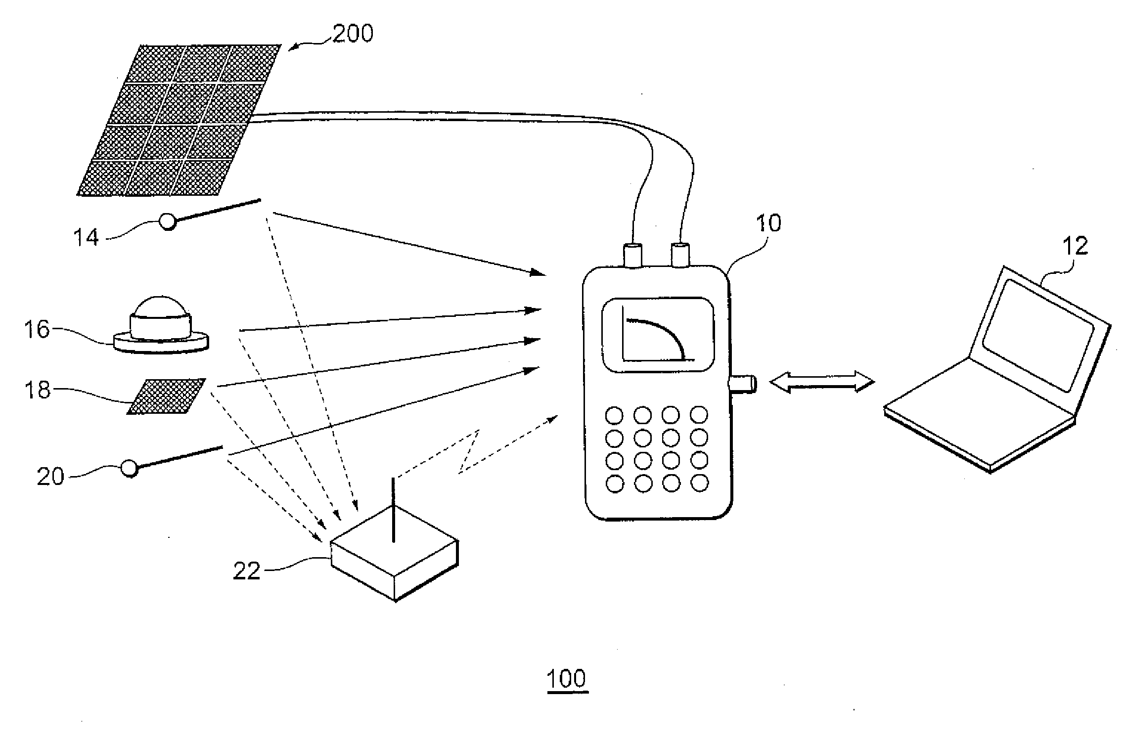
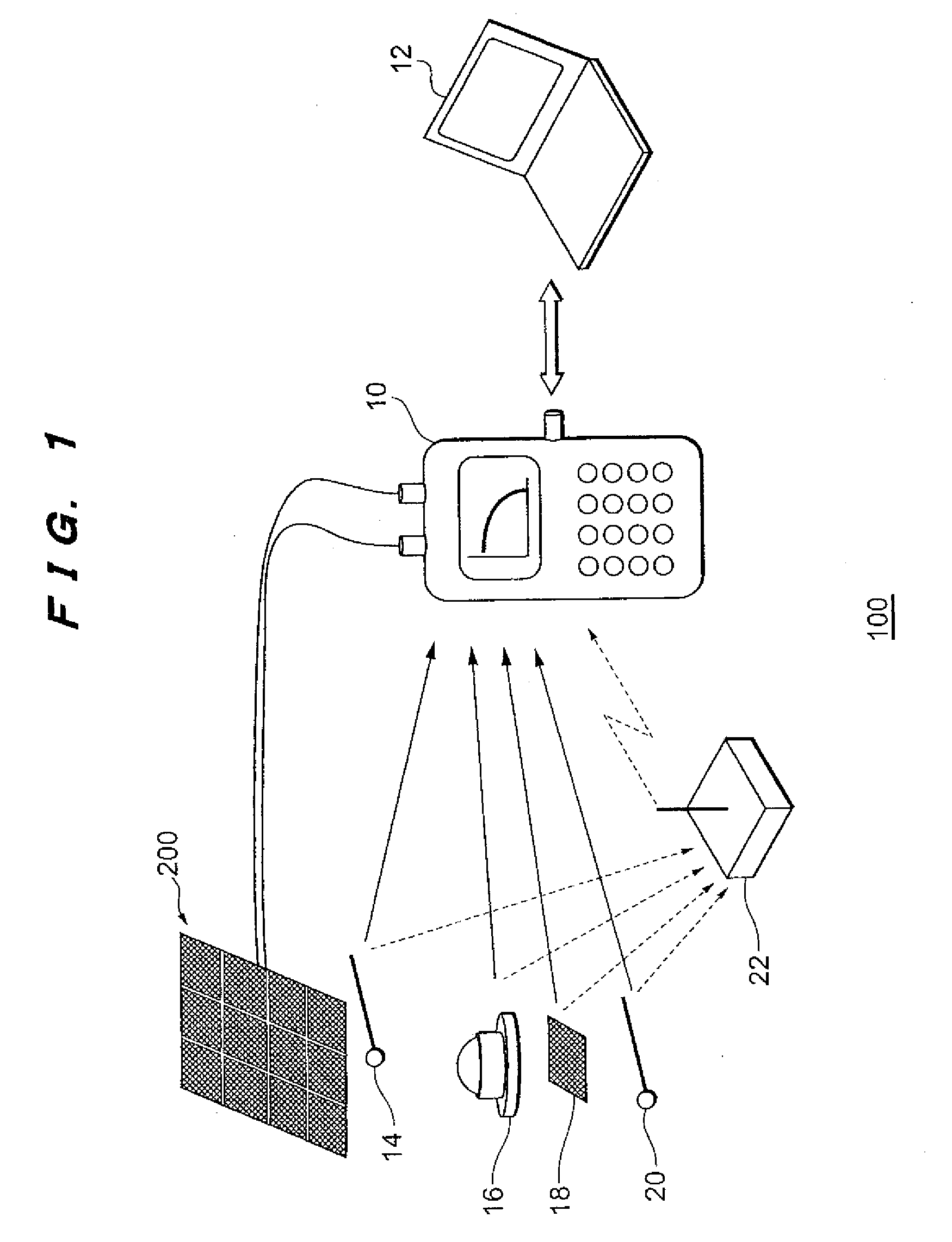
[0034]FIG. 1 is a diagram explaining the configuration of a solar cell module characterization system according to an embodiment of the present invention. The characterization system 100 shown in FIG. 1 is for performing the characterization of a solar cell module 200, and is configured from a characterization apparatus 10, a computer 12, thermometers 14, 20, an actinometer 16, and a reference cell 18.

[0035]The characterization apparatus 10 is connected to the solar cell module 200 via a wiring, and evaluates the characteristics of the solar cell module and displays the result of such evaluation. The characterization apparatus 10 is connected to the computer 12 via a fixed line such as USB (universal Serial Bus) or a wireless communication means, and is able to transfer the measured characteristic value or the evaluation result to the computer 12. The characterization apparatus 10 of...


PUM


Abstract

The objective is to perform a more detailed failure diagnosis of a photovoltaic device. Provided is a photovoltaic device characterization apparatus including a measurement unit (30, 36, 38, 40, 42, 44, 46, 48, 50) for measuring current-voltage characteristic of a photovoltaic device, a conversion unit (30) for converting the current-voltage characteristic measured with the measurement unit into a prescribed reference condition, a memory (52) for storing a plurality of reference characteristics, and a determination unit (30) for comparing the current-voltage characteristic converted into the reference condition and the reference characteristics read from the memory, and determining to which one of the reference characteristics the current-voltage characteristic is closest.

Description

TECHNICAL FIELD[0001]The present invention relates to technology for characterizing a photovoltaic device.BACKGROUND ART[0002]In recent years, with global environmental problems attracting attention, photovoltaic systems using solar energy, which is known to be inexhaustible and clean energy, are becoming popular. Japan holds the greatest global market share of photovoltaic systems and, as a part of the domestic countermeasures against global warming, the introduction of solar power systems corresponding to an electric-generating capacity of 4,820,000 kW by the year 2010 is targeted.[0003]Pursuant to the diffusion of photovoltaic systems in general households, technology for maintaining and managing the system is becoming important. For example, among the individual solar cells configuring the system, there are cases where certain solar cells are not able to obtain the prescribed output that was initially contemplated due to wiring errors during the installation, influence from shad...

Claims


Application Information

Patent Timeline
Patent Type & Authority Applications(United States)
IPC IPC(8): H01L31/04
CPCH01L31/02021H02S50/10Y02E10/50Y02B10/14Y02B10/10
Inventor HASEGAWA, TOSHIKAZUKATO, TADASHI
Owner EKO INSTR
Why Eureka
Try Eureka