Packaging substrate structure and manufacturing method thereof
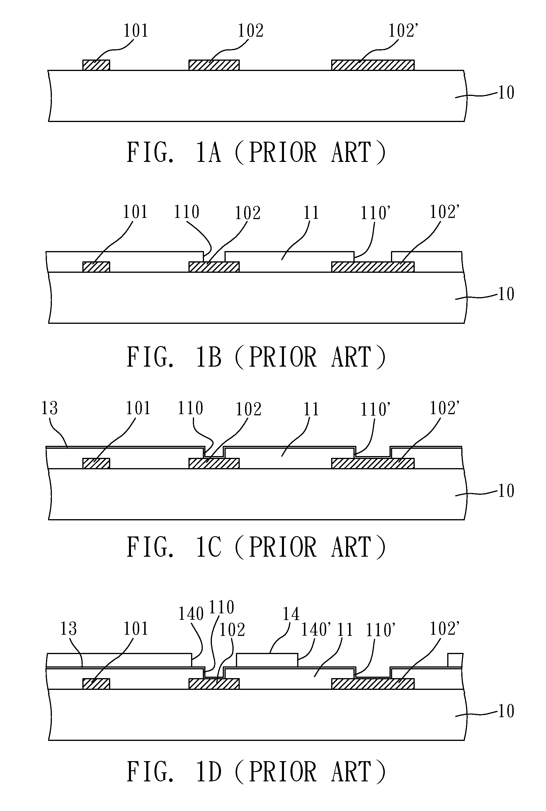
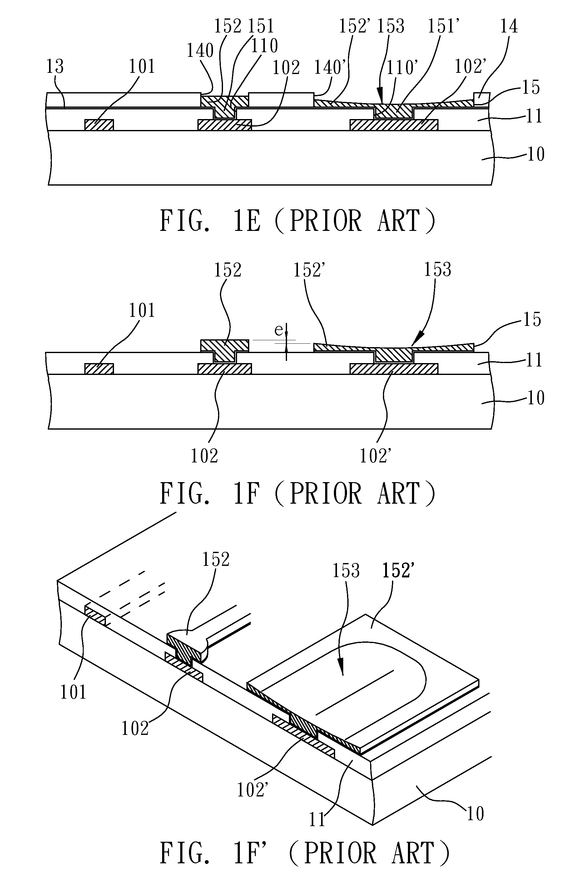
a technology of packaging substrate and manufacturing method, applied in the direction of electrical apparatus construction details, association of printed circuit non-printed electric components, printed element electric connection formation, etc., can solve the problems of poor electrical connection, poor impedance control, and rather difficult processing, so as to prevent poor electrical connection and poor impedance control
- Summary
- Abstract
- Description
- Claims
- Application Information
AI Technical Summary
Benefits of technology
Problems solved by technology
Method used
Image
Examples
first embodiment
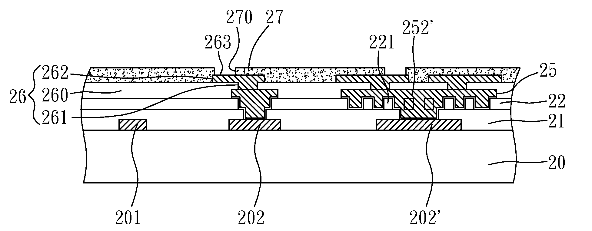
[0038]FIGS. 2A to 2F are views showing a manufacturing method of a packaging substrate structure according to a first embodiment of the present invention.
[0039]As shown in FIG. 2A, a carrier layer 20 is provided, and a patterned circuit layer is disposed on at least a surface of the carrier layer 20, wherein the patterned circuit layer has a plurality of circuits 201 and first electrical connection terminals 202, 202′. The carrier layer 20 is one of a core board and a dielectric layer of a multi-layer packaging substrate. At least a first dielectric layer 21 is formed on the patterned circuit layers 201, 202, 202′ and at least a surface of the carrier layer 20. A plurality of first vias 210, 210′ are formed in the first dielectric layer 21, allowing surfaces of the first electrical connection terminals 202, 202′ to be exposed from the first vias 210, 210′.
[0040]As shown in FIG. 2B, a second dielectric layer 22 is formed on the first dielectric layer 21. A plurality of small-dimensio...
second embodiment
[0047]FIGS. 3A to 3D are cross-sectional views showing a manufacturing method of a packaging substrate structure according to a second embodiment of the present invention. The second embodiment is different from the first embodiment in that the first and second circuit layers of the second embodiment are formed through a full additive process.
[0048]As shown in FIG. 3A, a structure similar to that of FIG. 2B is shown. A patterned circuit layer is disposed on the surface of a carrier layer 30. The patterned circuit layer comprises a plurality of circuits 301 and first electrical connection terminals 302, 302′. The carrier layer 30 is one of a core board and a dielectric layer of a multi-layer packaging substrate. A first dielectric layer 31 is formed on the surfaces of the carrier layer 30 and the patterned circuit layers 301, 302, 302′. A plurality of first vias 310, 310′ are formed in the first dielectric layer 31 to expose a portion of the first electrical connection terminals 302,...
PUM
| Property | Measurement | Unit |
|---|---|---|
| Dielectric polarization enthalpy | aaaaa | aaaaa |
| Shape | aaaaa | aaaaa |
| Electrical conductor | aaaaa | aaaaa |
Abstract
Description
Claims
Application Information
 - R&D
- Intellectual Property
- Life Sciences
- Materials
- Tech Scout
- Unparalleled Data Quality
- Higher Quality Content
- 60% Fewer Hallucinations
Browse by: Latest US Patents, China's latest patents, Technical Efficacy Thesaurus, Application Domain, Technology Topic, Popular Technical Reports.
© 2025 PatSnap. All rights reserved.Legal|Privacy policy|Modern Slavery Act Transparency Statement|Sitemap|About US| Contact US: help@patsnap.com


