Semiconductor die having a redistribution layer

Active Publication Date: 2009-01-01
TAIWAN SEMICON MFG CO LTD
View PDF35 Cites 4 Cited by
  • Summary
  • Abstract
  • Description
  • Claims
  • Application Information

AI Technical Summary

Benefits of technology

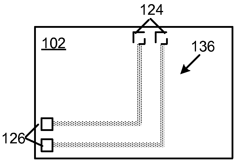
[0041]It is understood that using the above-described redistribution layer process steps, one or more die bond pads may be redistributed from any first location to any second location on a semiconductor die 102 by a redistribution layer across the die formed at the wafer level. Referring now to FIG. 12, at the completion of the above-described steps, the die 102 may be mounted on a substrate 160. The die 102 may be the only die mounted on a substrate 160, or the die 102 may be mounted on substrate 160 along with one or more additional die 162 and passive components 164 as shown in FIG. 12. Thereafter, the die bond pads on die 102, and any other die, may be wire bonded to contact pads on substrate 160 using wire bonds 166 in a known wire bond process. In embodiments, the die and substrate together may function as a flash memory device 170, where die 102 may be a controller such as an ASIC or a flash memory die. The die 102 may be other than a controller or

Problems solved by technology

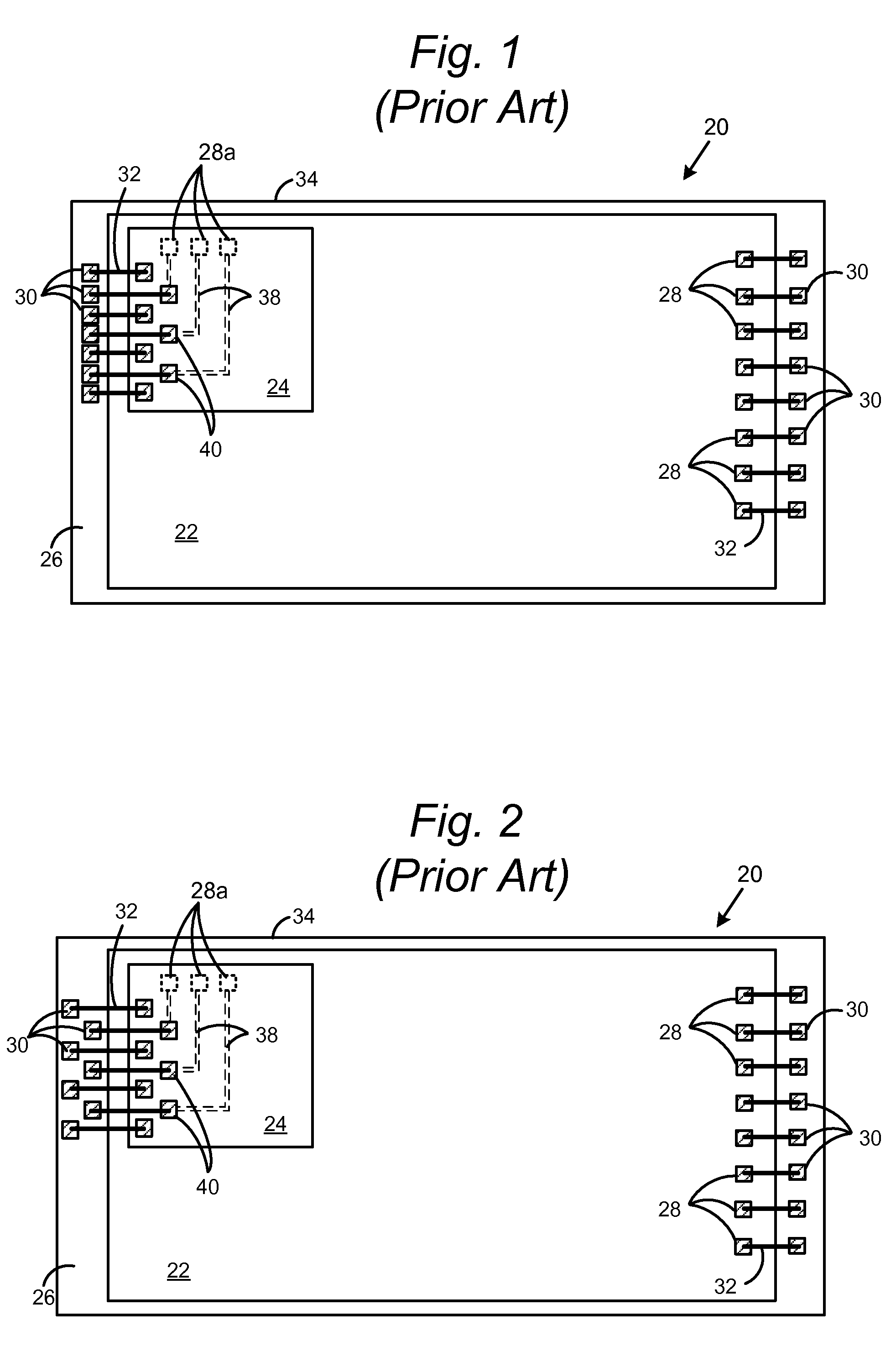
However, owing to the significant real estate limitations, there may only be room on the substrate for a wire bond connection along one edge of the die.
Current photolithography and other methods for forming a redistribution layer on semiconductor die are cumbersome, adding large numbers of process steps and expense to the fabrication process.

Method used


Image

  • Semiconductor die having a redistribution layer
  • Semiconductor die having a redistribution layer
  • Semiconductor die having a redistribution layer

Examples


Embodiment Construction

[0028]Embodiments of the present invention will now be described with reference to FIGS. 3 through 12, which relate to a multiple die redistribution layer for a semiconductor device and methods of forming same. It is understood that the present invention may be embodied in many different forms and should not be construed as being limited to the embodiments set forth herein. Rather, these embodiments are provided so that this disclosure will be thorough and complete and will fully convey the invention to those skilled in the art. Indeed, the invention is intended to cover alternatives, modifications and equivalents of these embodiments, which are included within the scope and spirit of the invention as defined by the appended claims. Furthermore, in the following detailed description of the present invention, numerous specific details are set forth in order to provide a thorough understanding of the present invention. However, it will be clear to those of ordinary skill in the art th...


PUM


Abstract

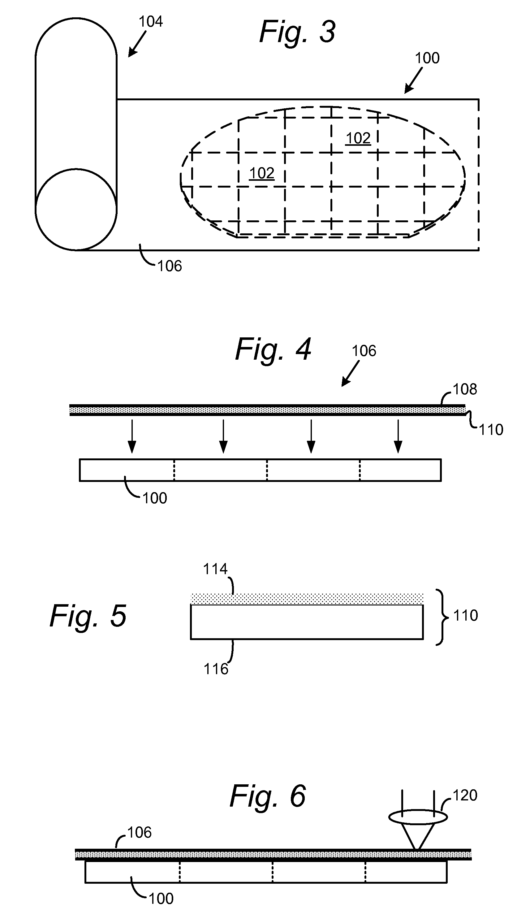
A semiconductor device having a redistribution layer, and methods of forming same, are disclosed. After fabrication of semiconductor die on a wafer, a tape assembly is applied onto a surface of the wafer, in contact with the surfaces of each semiconductor die on the wafer. The tape assembly includes a backgrind tape as a base layer, and a film assembly adhered to the backgrind tape. The film assembly in turn includes an adhesive film on which is deposited a thin layer of conductive material. The redistribution layer pattern is traced into the tape assembly, using for example a laser. Thereafter, the unheated portions of the tape assembly may be removed, leaving the heated redistribution layer pattern on each semiconductor die.

Description

CROSS-REFERENCE TO RELATED APPLICATION[0001]The following application is cross-referenced and incorporated by reference herein in its entirety:[0002]U.S. patent application Ser. No. ______ [Attorney Docket No. SAND-01257US0], entitled “Method of Fabricating a Semiconductor Die Having Redistribution Layer,” by Andrew Liao, et al., filed on even date herewith.BACKGROUND OF THE INVENTION[0003]1. Field of the Invention[0004]Embodiments of the present invention relate to a redistribution layer for a semiconductor device and methods of forming same.[0005]2. Description of the Related Art[0006]The strong growth in demand for portable consumer electronics is driving the need for high-capacity storage devices. Non-volatile semiconductor memory devices, such as flash memory storage cards, are becoming widely used to meet the ever-growing demands on digital information storage and exchange. Their portability, versatility and rugged design, along with their high reliability and large capacity, ...

Claims


Application Information

Patent Timeline
IPC IPC(8): H01L23/488
CPCH01L25/18H01L2224/48091H01L2924/07802H01L24/48H01L23/525H01L2224/48227H01L2225/0651H01L2225/06527H01L2225/06562H01L2924/01013H01L2924/01022H01L2924/01078H01L2924/14H01L2924/1433H01L2924/19105H01L23/49833H01L2924/00014H01L2924/00H01L24/97H01L2224/023H01L2224/05554H01L2224/32145H01L2224/73265H01L2224/94H01L2224/97H01L2924/1438H01L2924/1531H01L2924/181H01L2224/85H01L2224/03H01L2924/00012H01L2224/45099H01L2224/45015H01L2924/207H01L2924/0001
Inventor LIAO, CHIEN-KOCHIU, CHIN-TIENCHIEN, JACK CHANGYU, CHEEMENTAKIAR, HEM
Owner TAIWAN SEMICON MFG CO LTD
Why Eureka
Try Eureka