Supercharge Your Innovation With Domain-Expert AI Agents!

Piezoelectric actuator, piezoelectric actuator device, lens barrel, optical device and manufacturing method thereof

a piezoelectric actuator and actuator technology, applied in the direction of generators/motors, instruments, optical elements, etc., can solve the problems of difficult to minimize and difficult to minimize the size of the piezoelectric actuator according to the above conventional art, and achieve the effect of simple structure and minimized siz

Active Publication Date: 2009-01-01
MAXELL HLDG LTD
View PDF8 Cites 18 Cited by
  • Summary
  • Abstract
  • Description
  • Claims
  • Application Information

AI Technical Summary

Benefits of technology

[0007]An object of the present invention is to solve such problems and to provide a piezoelectric actuator with simple structure and minimized size.

Problems solved by technology

However, there is a problem that the piezoelectric actuator according to the above conventional art is difficult to minimize its size due to complexity of its shape and mechanism.
Also, stacking directions of the respective piezoelectric elements are orthogonal respectively adds complexity wiring, at this point, it is hard to minimize.

Method used


Image

  • Piezoelectric actuator, piezoelectric actuator device, lens barrel, optical device and manufacturing method thereof
  • Piezoelectric actuator, piezoelectric actuator device, lens barrel, optical device and manufacturing method thereof
  • Piezoelectric actuator, piezoelectric actuator device, lens barrel, optical device and manufacturing method thereof

Examples


first embodiment

[0122]Below, embodiments of a piezoelectric actuator according to the present invention are explained with reference to accompanying drawings.

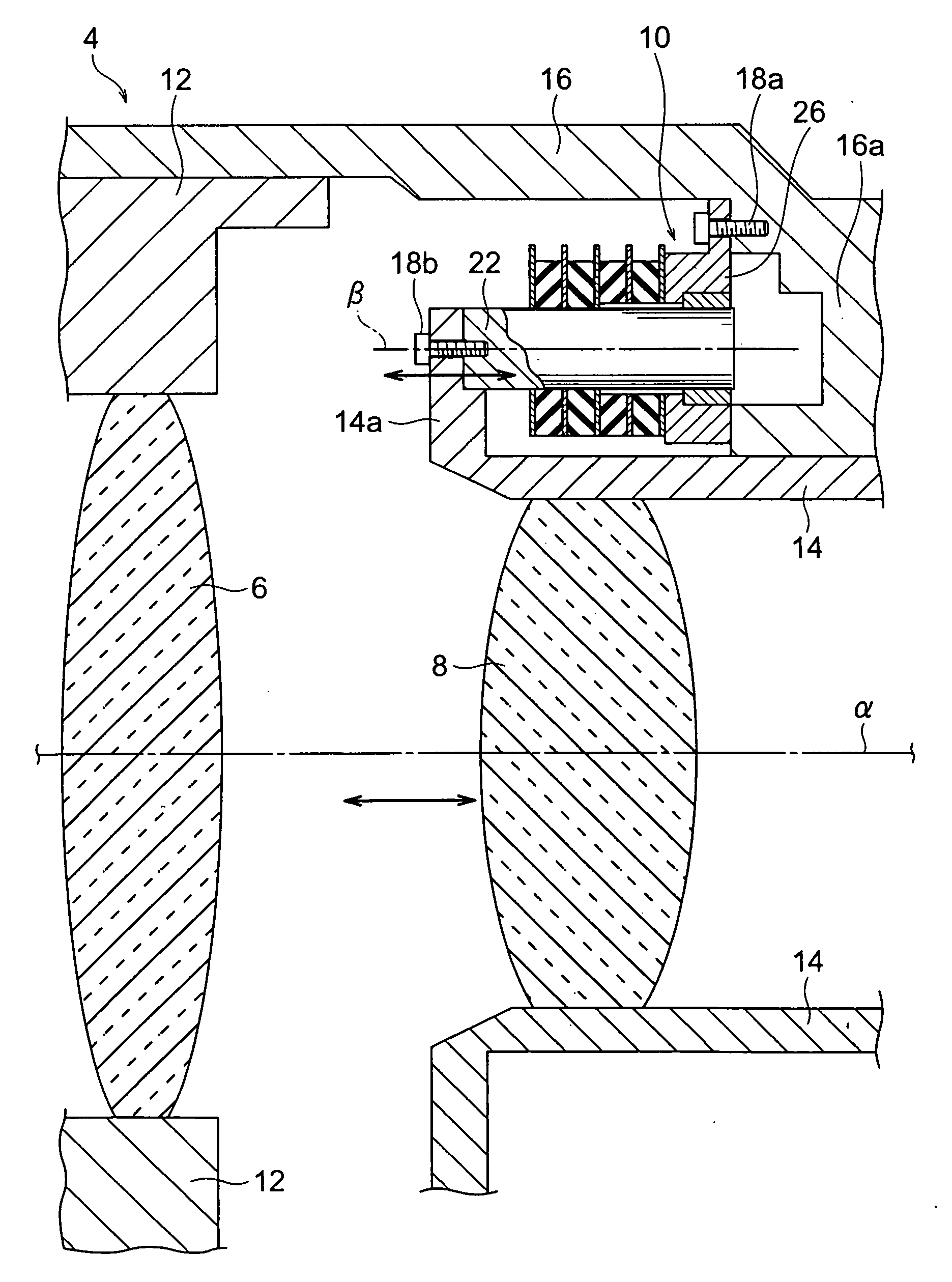
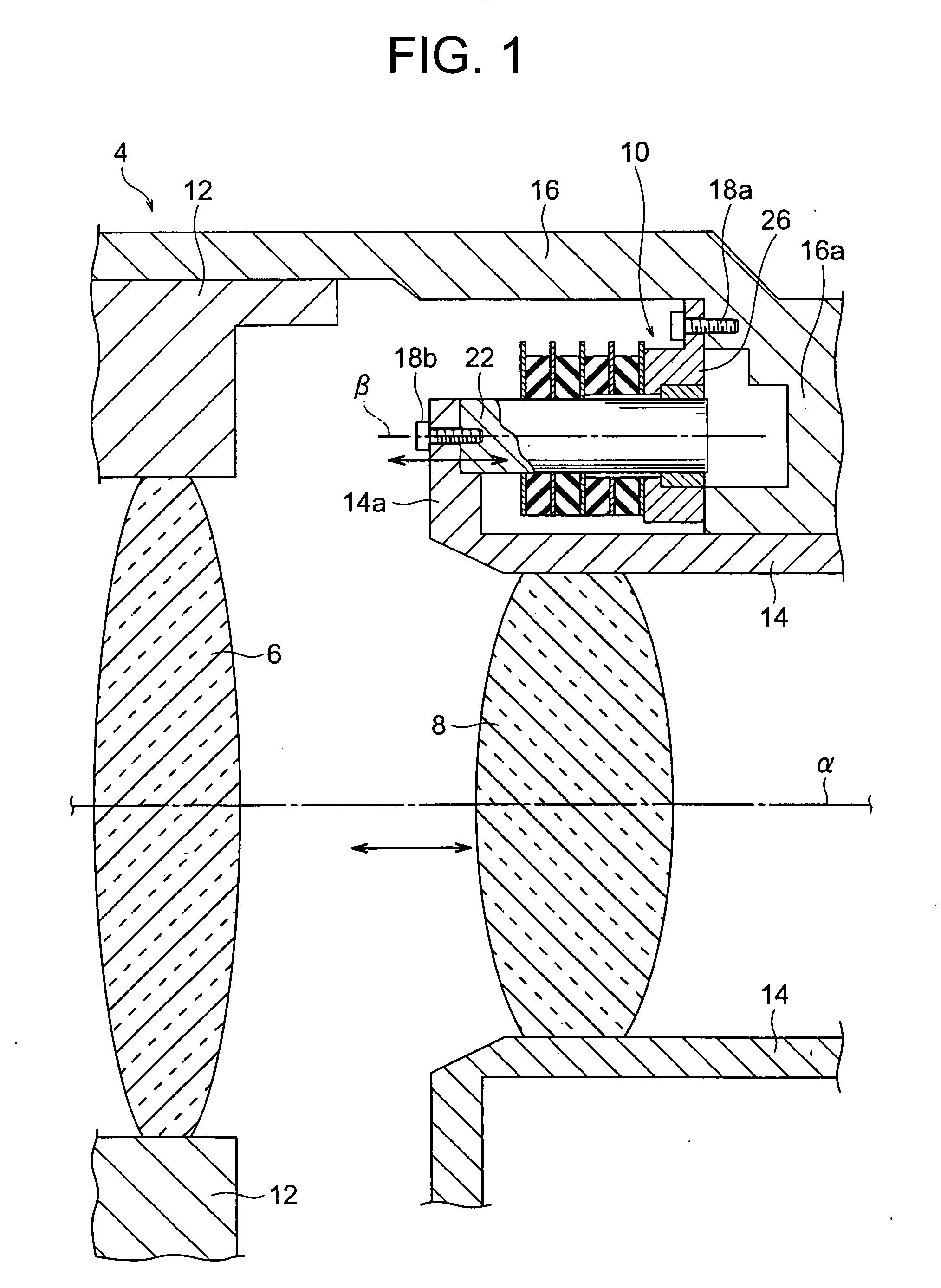
[0123]FIG. 1 is a drawing to explain a piezoelectric actuator 10 according to a first embodiment of the present invention, and a cross sectional view along an optical axis direction α of a lens barrel 4 to which the piezoelectric actuator 10 is equipped. In the vicinity of a center proton of the lens barrel 4, lens 6 and AF (auto-focal) adjust lens 8 are provided. The lens 6 is fixed on a lens holding frame 12, the holding frame 12 is located movably along an optical axis direction α of the lens 6 with respect to a fixing cylinder 16. An AF adjust lens 8 is fixed on an AF annulus 14. The AF annulus 14 is located movable along the optical axis α direction with respect to the fixing cylinder 16. The piezoelectric actuator 10 is fixed at a position where a peripheral side of the AF annulus 14 and an inner peripheral side of the fixing cylinder 16...

second embodiment

[0156]FIG. 5 is an enlarged cross sectional view of a piezoelectric actuator 10′ of a second embodiment. A driving portion 24′ has a constitution that six sheets of piezoelectric elements are stacked along the shaft core β direction. The driving portion 24′ is composed of a first clamping piezoelectric element portion 31a second clamping piezoelectric element portion 35 which clamp the output rod 22 and release from clamping, and a driving piezoelectric element portion 33 which expands and contracts along the shaft core β direction so as to move the output rod 22, and these are being multiple layered construction from tow sheet of piezoelectric elements, respectively. As mentioned below, in the second embodiment, by providing two kinds of clamping piezoelectric element portions, the output rod 22 can be driven with constantly clamping condition. Other structures other than the driving portion 24′ and a driving apparatus 56′ relating thereto, a driving signal generating portion 60′ a...

third embodiment

[0169]In the above two embodiments, a structure of driving one group of AF lens by using one piezoelectric actuator is explained. However, in a lens barrel having an optical system which is available to move a focal point such as VARI-FOCAL LENSES, when a focal distance is changed, a focal position is changed sometimes. In such VARI-FOCAL LENSES, it is preferable to compose that more than two-group AF lenses are driven, because, if it has the only one group of AF lens driven, an optical system becomes complex and a length of the lens barrel becomes longer.

[0170]FIG. 7 is a cross sectional view of a main section of a lens barrel comprising a piezoelectric actuator according to a third embodiment of the present invention. In a lens barrel 104 according to the present embodiment, three piezoelectric actuators 10a to 10c are provided.

[0171]In the lens barrel 104, a lens 106, a first AF (auto focal) focusing lens 8a, a second AF (auto focal) focusing lens 8b, a variable focal distance le...


PUM

PropertyMeasurementUnit
Frequencyaaaaaaaaaa
Piezoelectricityaaaaaaaaaa
Displacementaaaaaaaaaa

Abstract

A piezoelectric actuator comprises a first piezoelectric element pre-polarized towards a first direction and displaceable towards an about orthogonal direction with respect to said first direction, a second piezoelectric element pre-polarized towards a direction about parallel to the first direction and displaceable towards a direction about parallel to said first direction, a relative moving member clamped by displacement of said first piezoelectric element and relatively moves by displacement of said second piezoelectric element.

Description

BACKGROUND OF THE INVENTION[0001]1. Field of the Invention[0002]The present invention relates to a piezoelectric actuator which is available to obtain mechanical displacement by displacement of piezoelectric element.[0003]2. Description of the Related Art[0004]Presently, as a piezoelectric actuator, a rotation type represented by a type using progressive oscillating wave and a linear type represented by a type having clamping mechanism are known. The rotation type and the linear type are properly used depend on motion track, size, accuracy requirement and the like of a member which is a driven object. A linear type piezoelectric actuator can be used as a driving source for any members acting linear motion particularly, it is preferable, for example, a lens barrel with lenses which linearly moves in a body tube for auto focusing.[0005]As a linear type piezoelectric actuator according to conventional art, for example, it is known described in JP Patent Publication No. 55-100059. Such ...

Claims


Application Information

Patent Timeline
IPC IPC(8): H02N2/04H02N2/06G02B7/09H01L41/22G02B7/04H02N2/00
CPCG02B7/08H01L41/0835Y10T29/42H02N2/067H02N2/023H10N30/505
Inventor ASHIZAWA, TAKATOSHI
Owner MAXELL HLDG LTD
Features
  • R&D
  • Intellectual Property
  • Life Sciences
  • Materials
  • Tech Scout
  • Unparalleled Data Quality
  • Higher Quality Content
  • 60% Fewer Hallucinations
Learn More