In-Line Smoke Attenuator

a smoke attenuator and in-line technology, applied in the direction of fire alarms, separation processes, instruments, etc., can solve the problems of reducing the amount of sample air drawn from the region being monitored, premature failure, and problems such as the smoke detection apparatus

Active Publication Date: 2009-01-01
GARRETT THERMAL SYST LTD
View PDF11 Cites 51 Cited by
  • Summary
  • Abstract
  • Description
  • Claims
  • Application Information

AI Technical Summary

Benefits of technology

[0061]Embodiments of this aspect of the invention have the advantage that the ratio of filtered air to

Problems solved by technology

A problem can be encountered with such smoke detection apparatus if they are continuously exposed to the relatively high levels of background pollution in the air that can exist in some environments.
Background smoke pollution can cause soiling of components of the detector leading to premature failure, for example due to clogging of air paths or changes in the optical properties of the detection chamber itself.
However, as conventional dust filters clog they begin to remove more particles from the air and will eventually begin filtering out smoke particles (or other small particles of interest).
This can be a problem because such filters start undesirably removing smoke particles before the flow rate changes appreciably.
The result is that the filter may be removing an unknown proportion of smoke, but this is not detectable using flow-meters.
Dilution can be used to effectively reduce the conce

Method used


Image

  • In-Line Smoke Attenuator
  • In-Line Smoke Attenuator
  • In-Line Smoke Attenuator

Examples


Embodiment Construction

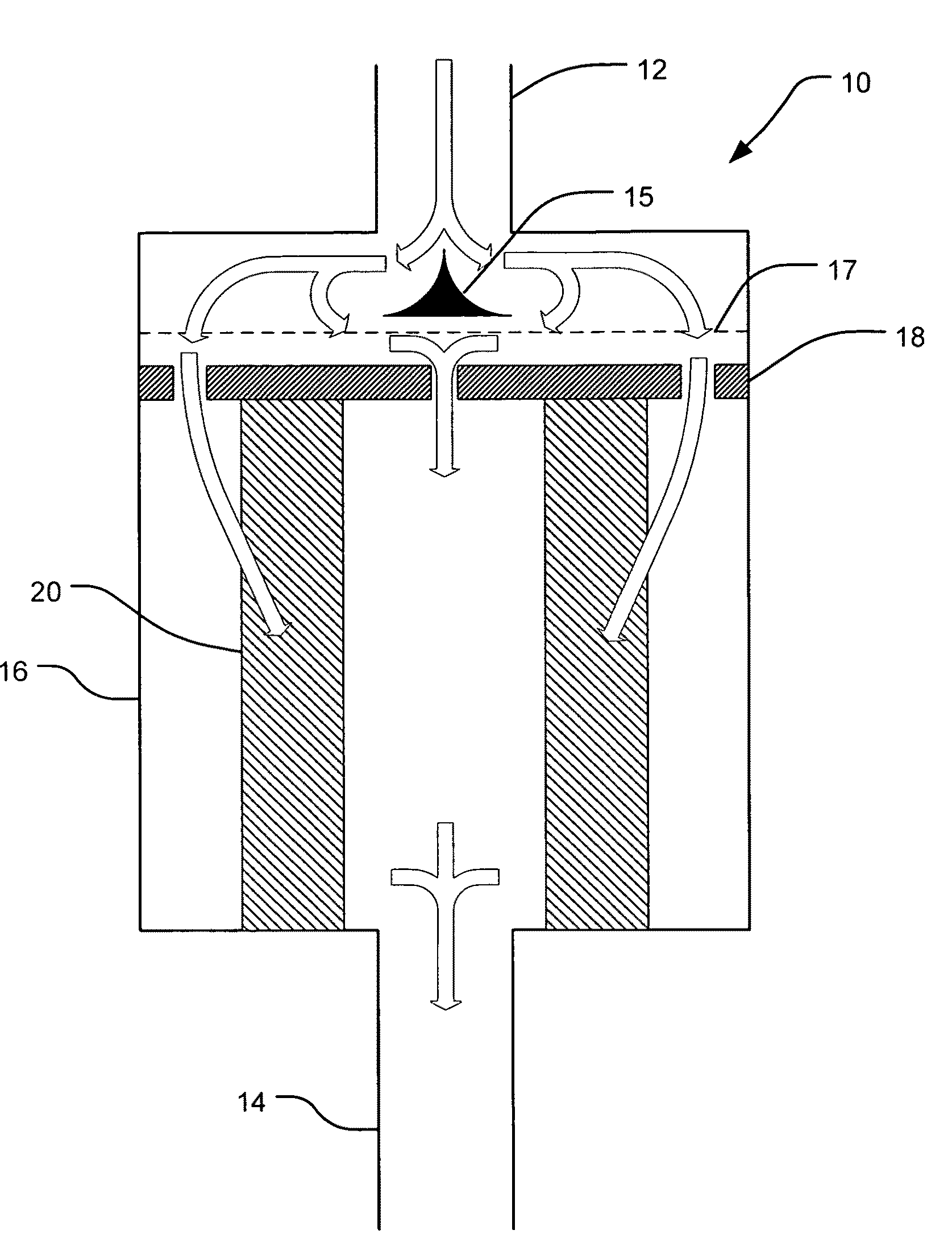
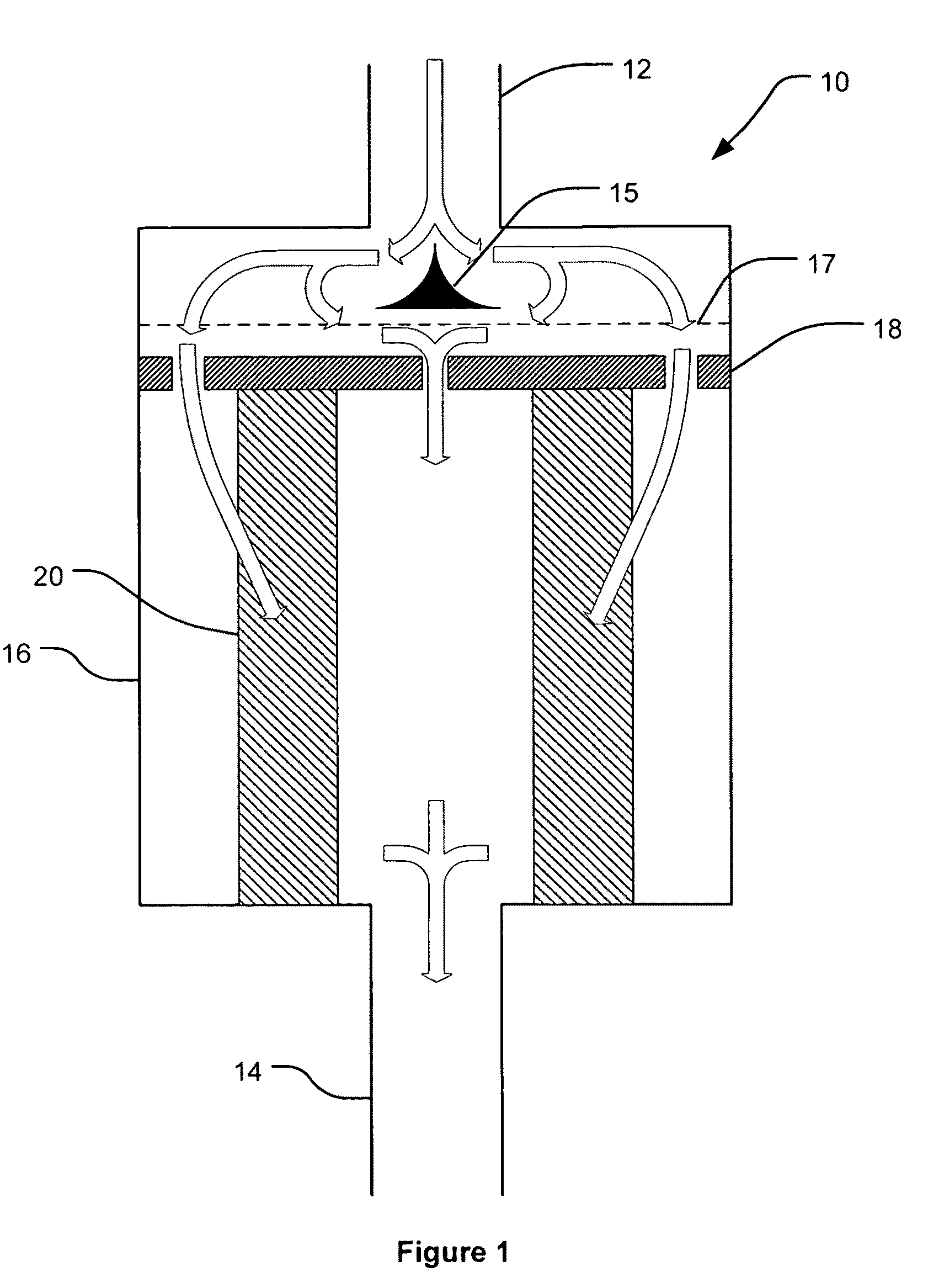
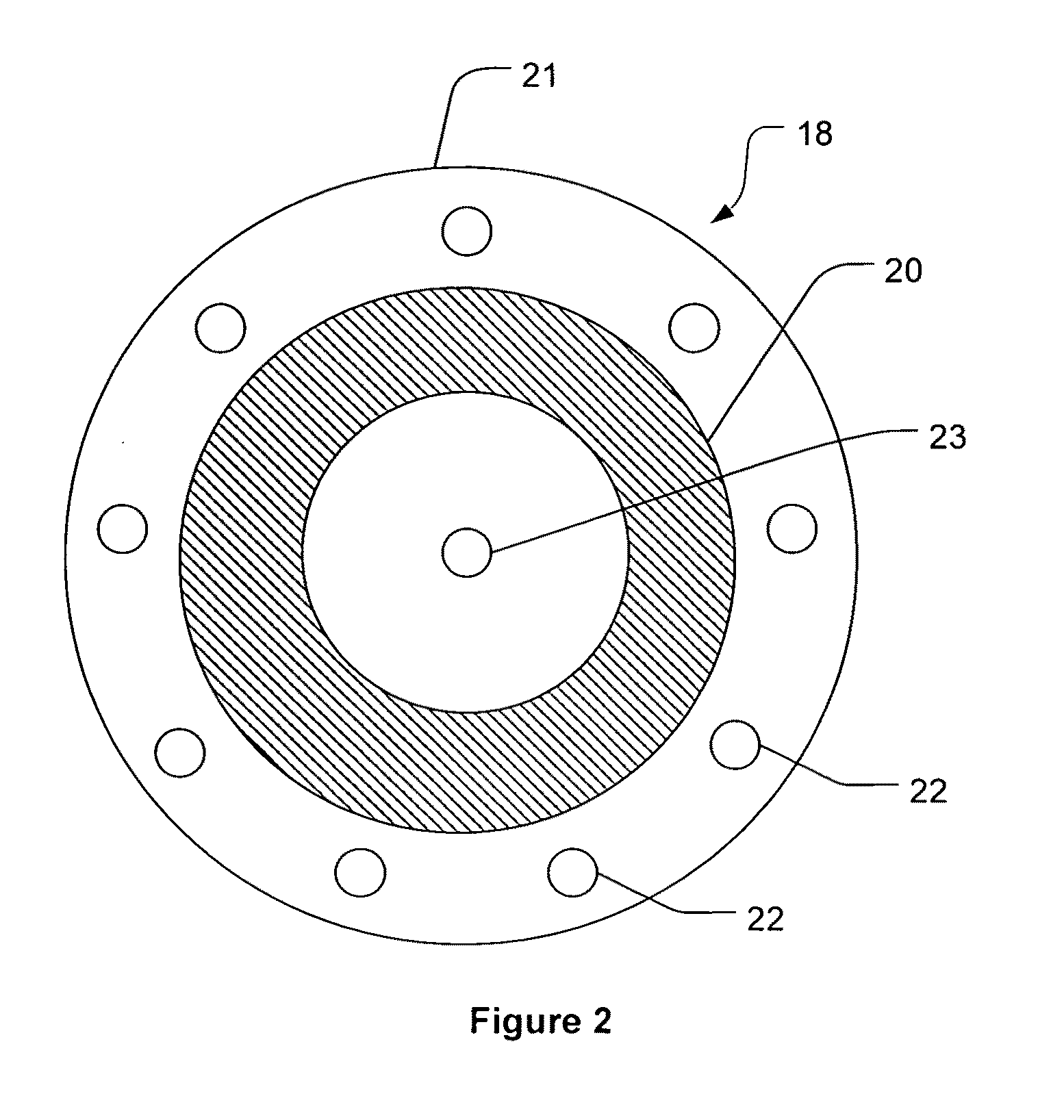
[0069]In FIG. 1 filtering apparatus 10, hereinafter termed a “smoke attenuator” is shown, having an inlet 12, an outlet 14, and a housing 16. Within the housing 16 is a flow separator 18 (shown in FIG. 2) and a filter 20 (shown in FIGS. 1, 2 and 3). In the present example the flow separator 18 is a plate 21 having a number of apertures 22 and 23 formed in it. These apertures are shown in greater detail in FIG. 2. In this example the flow separator separates the single flow of air entering the inlet into a filtered sub-flow (air passing through apertures 22) and an unfiltered sub-flow (air passing through aperture 23). The filtered and unfiltered sub-flows recombine in the area after the filter, before exiting the filter outlet 14. A flow distributor 15 may be placed near the inlet 12 to assist in distributing the flow evenly within the housing. An insect screen 17, e.g. formed from a wire mesh, may also be placed within the housing to prevent insects and very large particulate mater...


PUM

PropertyMeasurementUnit
Timeaaaaaaaaaa
Flow rateaaaaaaaaaa
Diameteraaaaaaaaaa

Abstract

In one form the present invention provides an apparatus in an airflow path before a particle detector, wherein the apparatus removes a substantially constant proportion of all sizes of airborne particles from the airflow over time. In an example the apparatus includes a flow splitting arrangement configured to divide a fluid flow into a plurality of sub-flows, the splitting arrangement 10 including means for defining a plurality of substantially identically dimensioned flow apertures configured to direct a portion of the fluid into a respective sub-flow.

Description

FIELD OF INVENTION[0001]The present invention relates to an improved method and apparatus for particle detection. In a preferred form, the present invention relates to a method and apparatus for filtering an air sample before applying it to a particle detector.[0002]It will be convenient to describe the invention as applied to smoke detection, however the invention should not be construed as being limited to this exemplary field of use.BACKGROUND OF THE INVENTION[0003]Particle detectors are often used to warn of the presence of smoke emanating from a potential or incipient fire. Particle detectors of the scattering light type operate by exposing an air sample, that is drawn from an area being monitored, to light, and detecting light scattered from any particles in the air. Air, for example from a factory or office, usually contains some level of particles, and the detector can be set to alarm at certain levels which are higher than background particle levels, and are believed to be ...

Claims


Application Information

Patent Timeline
IPC IPC(8): G08B17/10G01N1/00
CPCB01D46/0012B01D46/0043B01D46/2403B01D46/442G01N2001/227G01N1/2258G01N2001/2223G01N2001/2264G01N1/2205B01D35/00G08B17/10G01N1/18G08B17/12
Inventor KNOX, RONMARTIN, SCOTT JAMES
Owner GARRETT THERMAL SYST LTD
Why Eureka
Try Eureka