
Method of Moving Tracks, Method and Apparatus of Recording and/or Playback

a technology of moving tracks and recording equipment, applied in the field of moving tracks, can solve the problems of difficult to prevent the recording medium from colliding with the bottom surface of the near field lens, the limit of the diameter of the light beam, and the increase of the probability of collision, so as to minimize the error

Inactive Publication Date: 2009-01-01
LG ELECTRONICS INC
View PDF8 Cites 8 Cited by
  • Summary
  • Abstract
  • Description
  • Claims
  • Application Information

AI Technical Summary

Benefits of technology

The present invention provides a method and apparatus for recording and playback that overcomes limitations and disadvantages of related art. The technical effects of the invention include an efficient method of moving tracks and minimizing errors due to collision while lens moves the tracks. The method includes changing a gap between a lens and a recording medium in correspondence with a distance of moving tracks when the lens moves from one track to another. The gap control signal may be generated by the light beam reflected from the recording medium and applied to the lens to control the gap. The offset may be stepwise changed according to the distance of moving tracks and the level of the offset may be proportional to the distance of moving tracks. The invention allows for faster and more accurate track movement and recording.

Problems solved by technology

However, since a far field recording head using a general lens has a light diffraction limitation, there is a limitation to reduce the diameter of the light beam.
However, the conventional apparatus has the following problems.
Accordingly, in consideration of axial vibration of the recording medium or a tilt at the time of the drive of a pickup, it is difficult to prevent the recording medium from colliding with the bottom surface of the near field lens.
In particular, in order to seek a desired point of the recording medium, while lens part moves the tracks by moving the light beam generated at the optical pickup from a current track to a target track, a probability of collision increases.

Method used


Image

  • Method of Moving Tracks, Method and Apparatus of Recording and/or Playback
  • Method of Moving Tracks, Method and Apparatus of Recording and/or Playback
  • Method of Moving Tracks, Method and Apparatus of Recording and/or Playback

Examples


first embodiment

of Method of Moving Tracks

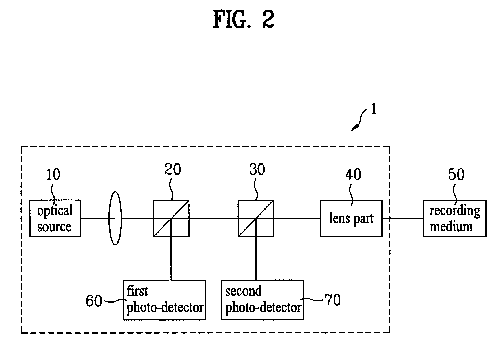
[0071]A method of moving tracks according to a first embodiment of the present invention will be described in detail with reference to FIGS. 9 and 10. The method of moving tracks according to the present invention includes a track seeking method (also referred to as “rough seek”) for moving the optical pickup 1 by a coarse motor such as the sled servo drive unit 6 and a method (also referred to as “fine seek”) for driving the lens part 40 by a fine drive unit in the optical pickup 1, such as an actuator (not shown). The optical pickup 1 or the lens part 40 may vertically move when the optical pickup 1 or the lens part 40 moves in the radial direction.

[0072]In the present specification, a case where the gap servo is performed at the gap G corresponding to 20% of the near field limitation in which a signal is easiest observed in the near field limitation (λ / 4 may be the near field limitation, as described above) will be described. As shown in FIG. 9, when the...

second embodiment

of Method of Moving Tracks

[0082]A method of moving tracks according to a second embodiment of the present invention will be described in detail with reference to FIG. 11. In the present embodiment, only a portion different from the first embodiment will be described.

[0083]FIG. 11 shows a variation in the gap between the lens part 40 and the recording medium 50 in a recording and / or playback method according to an embodiment of the present invention. As shown, in the recording and / or playback method according to the present invention, the method of moving tracks may include four steps. Hereinafter, the steps will be sequentially described in detail.

[0084]A first step is a recording and / or playback step in a recording and / or playback apparatus. This step indicates the step of playback data from the inserted recording medium 50 or recording data on the recording medium 50, that is, a driving state before a track seek command is input. In the recording and / or playback step, the lens par...

third embodiment

of Method of Moving Tracks

[0098]A method of moving tracks according to a third embodiment of the present invention will be described in detail with reference to FIGS. 12 to 14. In the present embodiment, only a portion different from the second embodiment will be described.

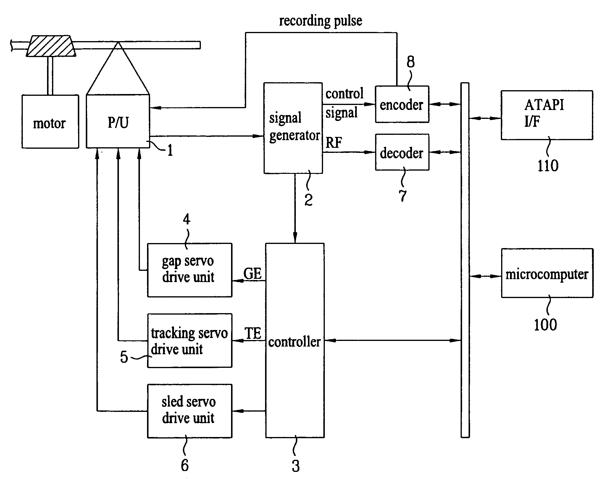
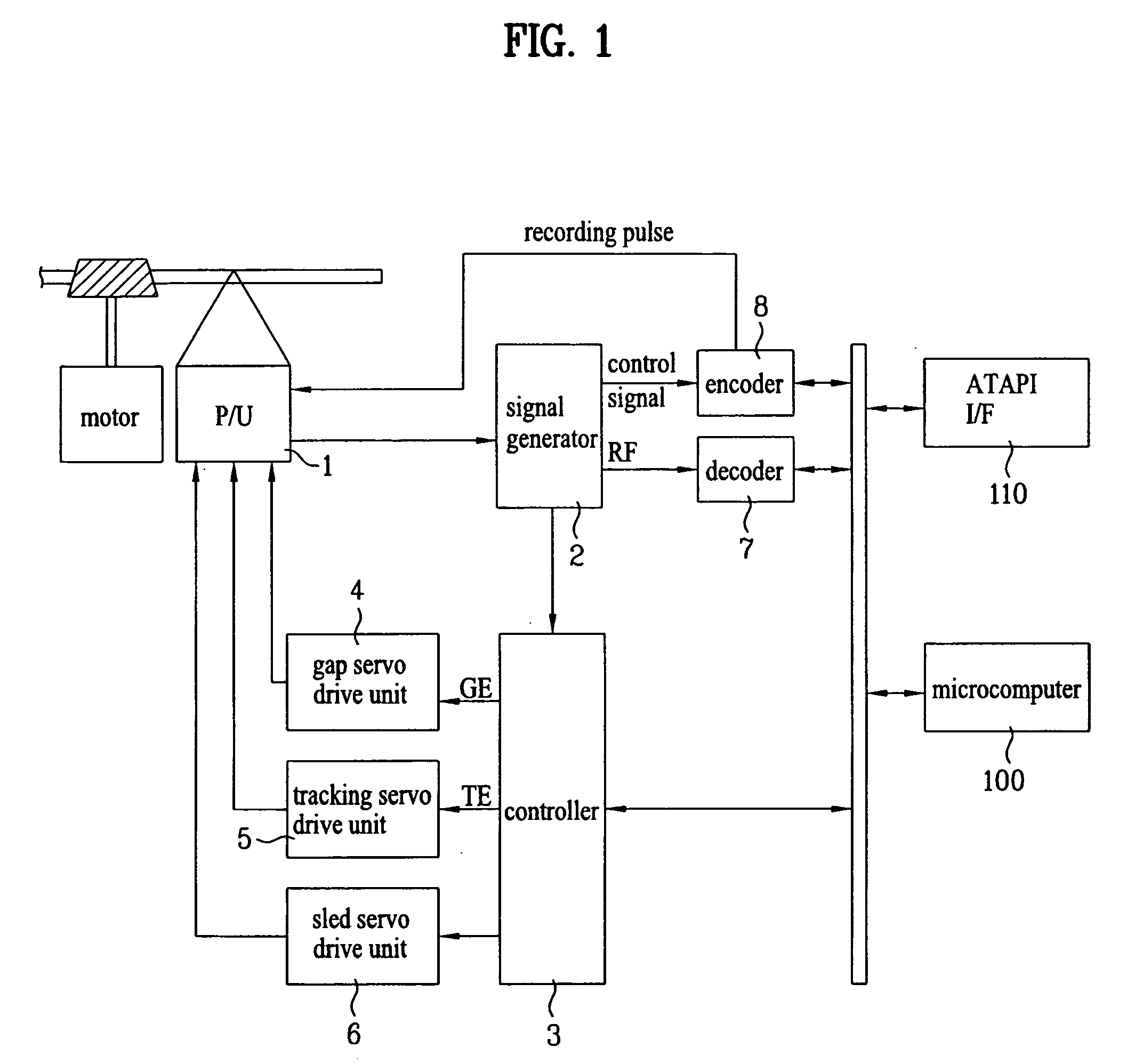
[0099]Prior to the description of the method, a recording and / or playback apparatus which can be used in the present embodiment and more particular the structure of a controller 3 will be-described in detail. In the recording and / or playback apparatus shown in FIG. 1, the controller 3 may be configured as shown in FIG. 12.

[0100]FIG. 12 is a view showing in detail an internal structure of the controller 3 according to an embodiment of the present invention. A servo-equalizer 301 receives a gap error signal GE or a tracking error signal TE from the signal generator 2 of FIG. 1, and adjusts a compensation gain to compensate for an error according to feed-back control. Similar to the method of the second embodiment, t...


PUM

PropertyMeasurementUnit
diameteraaaaaaaaaa
diameteraaaaaaaaaa
distanceaaaaaaaaaa

Abstract

A recording and / or playback apparatus and method and a method of moving tracks, and more particularly, an apparatus and method for efficiently seeking a track and recording and / or playback data on / from a recording medium, are disclosed. The method of moving tracks includes changing a gap between a lens part and a recording medium in correspondence with a distance of moving tracks when the lens moves from a current track to another track. Accordingly, it is possible to minimize or prevent the collision between the lens part and the recording medium and to efficiently seek the track to perform recording / reproduction when recording and / or playback data on / from the recording medium.

Description

TECHNICAL FIELD [0001]The present invention relates to a method of moving tracks and method and apparatus of recording and / or playback, more particularly, to an apparatus and method for efficiently moving tracks and recording and / or playback data on / from a recording medium.BACKGROUND ART [0002]Generally, an optical recording and / or playback apparatus records / reproduces data on / from a disc such as a compact disc (CD) or a digital versatile disc (DVD). As the preferences of consumers have changed, a technology for processing a high-definition moving image is required. In addition, as a moving-image compression technology has been developed, a high-density recording medium is required. A technology related to an optical head, that is, an optical pickup, is necessary for developing the high-density recording medium.[0003]The recording density of the recording medium depends on the diameter of a light beam irradiated onto a recording layer of the recording medium. That is, as the diamete...

Claims


Application Information

Patent Timeline
Patent Type & Authority Applications(United States)
IPC IPC(8): G11B7/00
CPCB82Y10/00G11B7/08505G11B7/08523G11B2007/13727G11B7/08541G11B7/1201G11B7/1387G11B7/08535G11B7/121
Inventor SEO, JEONG KYOKIM, JIN A
Owner LG ELECTRONICS INC
Learn More