
A Method and System For Obtaining Path Maximum Transfer Unit in Network

Inactive Publication Date: 2009-01-01
HUAWEI TECH CO LTD
View PDF14 Cites 25 Cited by
  • Summary
  • Abstract
  • Description
  • Claims
  • Application Information

AI Technical Summary

Benefits of technology

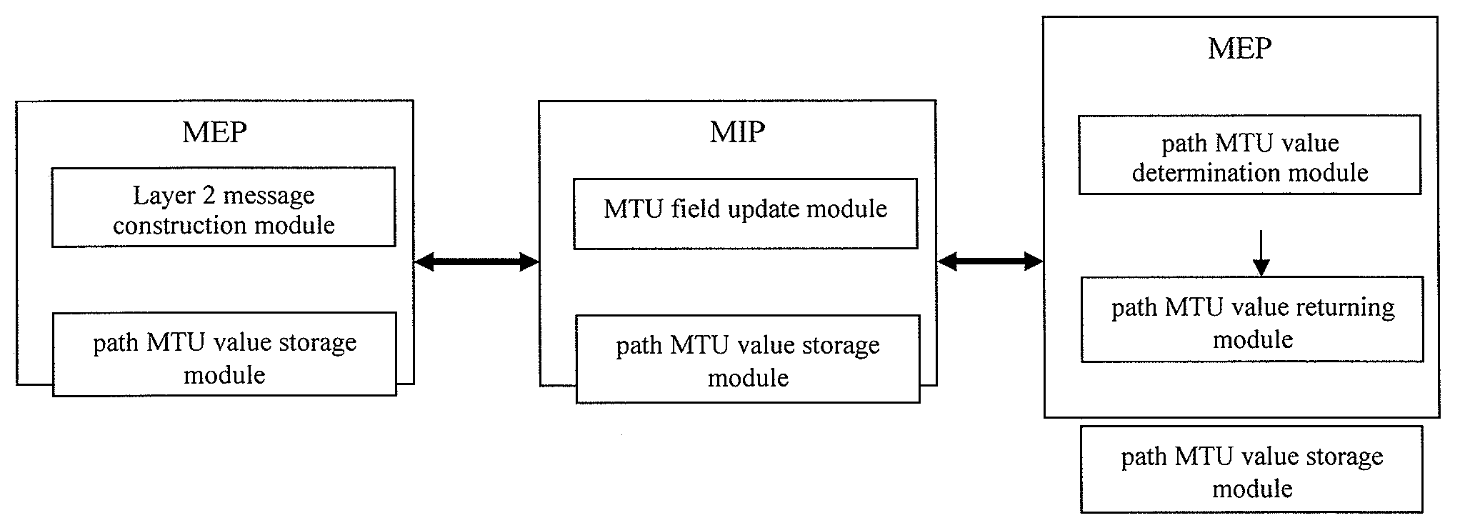
[0020]The objective of the present invention is to provide a method and system for obtaining a path maximum transmission unit which may be used in implementing OAM in the Ethernet, so that when implementing OAM in the Ethernet, the MTU of the path which an OAM message passes can be obtained and a corresponding path MTU can be obtained, thus ensuring that reliable transmission of the OAM message.
[0062]It can be seen from the inventive technical solution that the present invention obtains a value of a path MTU through the Ethernet OAM procedure, thereby avoiding the case that the transmitted OAM message can not be transmitted to a destination end because the size of the OAM message exceeding the MTU of the path during the transmission path operates normally. Thus, the present invention can efficiently improve the reliability of OAM message transmission as well as the reliability of implementing OAM functions in Ethernet.
[0063]The present invention can be applied to maintenance of the network operation. For example, when a user service is disconnected, the present invention can be used to determine the fault reason (e.g., if it is due to a message size exceeding the path MTU value) and locate the fault accurately.

Problems solved by technology

Generally, the slicing OAM messages results in complicated processing and degrades the network performance, while the discarding OAM messages leads to messages not being able to reach the destination.
Therefore, the above method can not be used for obtaining a corresponding path MTU during implementing OAM function.

Method used


Image

  • A Method and System For Obtaining Path Maximum Transfer Unit in Network
  • A Method and System For Obtaining Path Maximum Transfer Unit in Network
  • A Method and System For Obtaining Path Maximum Transfer Unit in Network

Examples


Embodiment Construction

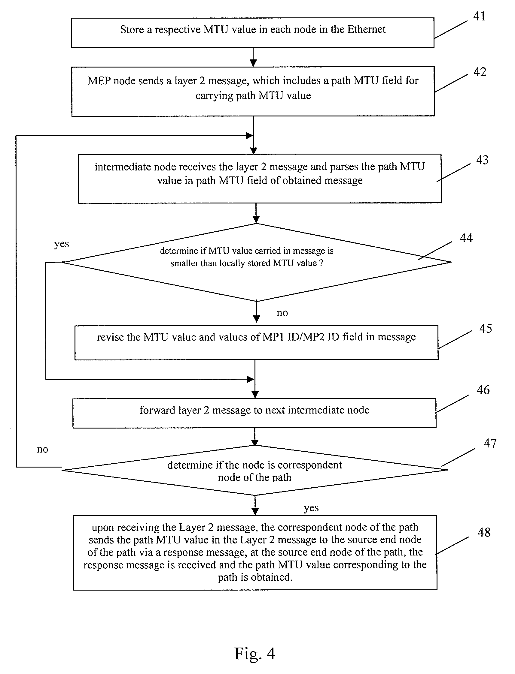
[0070]An essential principle of embodiments of the present invention is to use a Layer 2 message to detect a path MTU in a Layer 2 path, so that the path MTU value of a corresponding path in the Layer 2 network is obtained, it is possible to transmit a message over the Layer 2 path according to the path MTU, and a transmission reliability of the Layer 2 message including OAM message is ensured.

[0071]In the following, the reason for needing the path MTU in the Ethernet will be explained in detail.

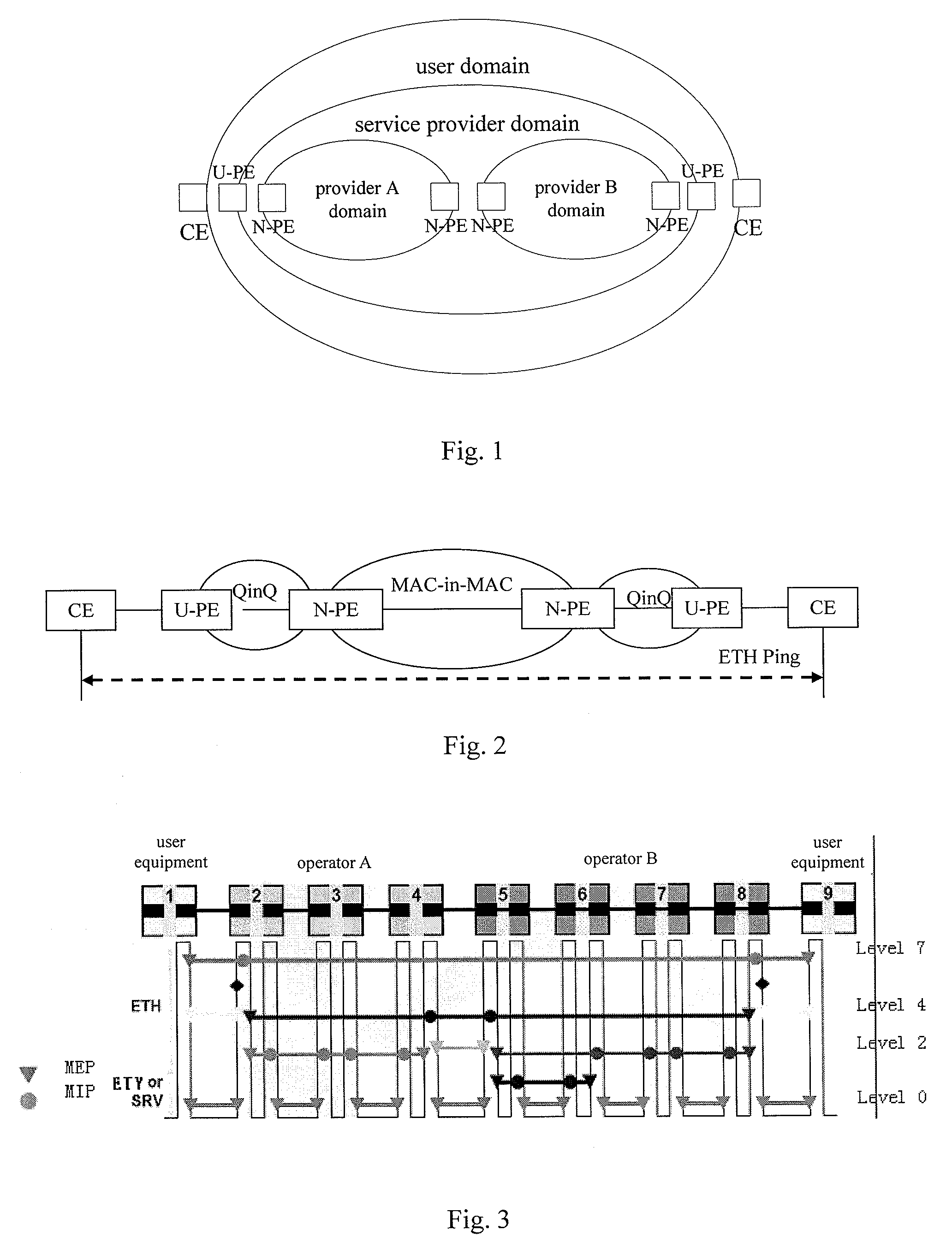
[0072]In the Ethernet, Ethernet service OAM functions realize an end-to-end connectivity fault management, such as the connectivity between CE and CE, through OAM message exchange. The process of realizing the connectivity management includes a link quality testing for a corresponding link. In the Ethernet, Layer 2 Ping function can be realized by a loopback function of the Ethernet OAM, thereby realizing the quality test of the corresponding link.

[0073]As shown in FIG. 2, when performing La...


PUM


Abstract

A method and system for obtaining path maximum transfer unit in network, include first, at the path start node sending the second layer message which carries the path MTU field for carrying path MTU value and at each node which the second layer message passed renewing the MTU value in the field according to the values preserved in each node; then, when the second layer message arrives at the path terminal node, regarding the MTU value being carried in the path MTU field in the second layer message as the path MTU value corresponding with the path. The present invention acquires the size of path MTU by use of Ethernet network OAM process, avoids the failure of transmitting the OAM message to object end caused by the reason that the size of transmitted OAM message exceeds the MTU of path when the route itself is normal. Therefore, the present invention can increase the reliability of OAM message transmission effectively, and assure the reliability of OAM function realization in Ethernet network.

Description

TECHNICAL FIELD OF THE INVENTION[0001]The present invention relates generally to network communication, and in particular to a technique for obtaining a path maximum transmission unit (MTU), in a network.BACKGROUND OF THE INVENTION[0002]With the development of the network communication technologies, Ethernet has gradually become the dominating technique for Local Area Network (LAN), because of its simple use and low price. Meanwhile, with the application of Gigabit and 10 Gigabit Ethernet, Ethernet is used in Metropolitan Area Network and Wide Area Network, gaining much wider application.[0003]In order to make it easier to perform operation, administration and maintenance for Ethernet, it is necessary to implement corresponding operation, administration and maintenance (OAM) mechanism over Ethernet, thereby to improve the capability of administrating and maintaining Ethernet and ensure robust operation of Ethernet.[0004]Currently, in Ethernet, functions of Ethernet OAM mainly includ...

Claims


Application Information

Patent Timeline
IPC IPC(8): H04L12/28
CPCH04L41/0659H04L41/0677H04L43/0829H04L47/36H04L43/087H04L47/10H04L43/0852
Inventor TENG, XINDONG
Owner HUAWEI TECH CO LTD
Learn More