Method and apparatus for manufacturing aluminum alloy strip for lithographic printing plates

a technology of lithographic printing plate and aluminum alloy, which is applied in the direction of manufacturing converters, printing form reproduction, furnaces, etc., can solve the problems that tibsub>2 /sub>particles having a particle size of 100 m or more cannot be completely eliminated, and the use of fine filtering means alone is not enough to prevent black streaks during casting for an extended period of time, so as to prevent the formation of black streaks

Inactive Publication Date: 2009-01-01
FUJIFILM CORP
View PDF2 Cites 12 Cited by
  • Summary
  • Abstract
  • Description
  • Claims
  • Application Information

AI Technical Summary

Benefits of technology

[0009]It is therefore an object of the present invention to provide a method of manufacturing aluminum alloy strip for use in the production of lithographic printing plate supports, which method is able to prevent the formation of black streaks even when casting is carried out for an extended period of time (i.e., even when continuous casting, such as the casting of more than 50 metric tons, is carried out). A further object of the invention is to provide an apparatus for manufacturing such aluminum alloy strip for use in the production of lithographic printing plate supports.
[0017]Based on the above findings, the inventors have conducted continuous casting tests using real aluminum melts, as a result of which they have discovered that, with the subsequently described inventive method of manufacturing aluminum alloy strip for lithographic printing plates, it is possible to prevent the formation of black streaks by coarse TiB2 particles having a size of 100 μm or more which are carried off downstream and become incorporated into the cast strip.
[0018]That is, with the inventive method of manufacturing aluminum alloy strip for lithographic printing plates described below, even when the circumstances indicated above as the first and second findings concerning the behavior of TiB2 particles downstream from the filtration device have arisen, it is possible to prevent the formation of black streaks by coarse TiB2 particles that are carried off downstream and become incorporated into the cast strip.
[0031]In the inventive method of manufacturing aluminum alloy strip for lithographic printing plates, coarse TiB2 particles having a size of 100 μm or more that have slipped through the filtering means settle to the bottom of the launder connected to the filtering means when casting is carried out for an extended period of time (i.e., during continuous casting, such as the casting of more than 50 metric tons). As a result, the coarse TiB2 particles do not reach the liquid level controlling means and the melt feed nozzle, making it possible to prevent the coarse TiB2 particles from being incorporated into the cast strip and forming black streaks. Moreover, because the launder has a length L of 4 m or less, there is no risk that the aluminum melt will undergo a decrease in temperature as it passes through the launder and a portion of the melt will begin to solidify.
[0032]Also, in the inventive method of manufacturing aluminum alloy strip for lithographic printing plates, by providing a means for trapping coarse TiB2 particles present in the aluminum melt at one or more place within the liquid level controlling means, coarse TiB2 particles 100 μm or more is size that have settled to the bottom of the launder and the liquid level controlling means can be prevented from flowing out due to, for example, changes in the flow velocity of the aluminum melt, becoming incorporated into the cast strip, and giving rise to black streaks.
[0033]Similarly, by providing a means for trapping coarse TiB2 particles present in the aluminum melt at one or more place within the melt feed nozzle, coarse TiB2 particles having a size of 100 μm or more that have settled within the melt feed nozzle can be prevented from flowing out due to changes in the flow velocity of the aluminum melt, becoming incorporated into the cast strip, and giving rise to black streaks.

Problems solved by technology

As noted above, the inventors have confirmed that, although using a fine filtering means to block the passage of coarse TiB2 particles is itself desirable for preventing black streaks, the use of a fine filtering means alone is not enough to prevent black streaks when casting is carried out for an extended period of time (i.e., during continuous casting, such as the casting of more than 50 metric tons).
In the course of carrying out casting over a long period of time (i.e., during continuous casting, such as the casting of more than 50 metric tons), the possibility that coarse TiB2 particles having a particle size of 100 μm or more will slip through such gaps cannot be entirely eliminated.

Method used


Image

  • Method and apparatus for manufacturing aluminum alloy strip for lithographic printing plates
  • Method and apparatus for manufacturing aluminum alloy strip for lithographic printing plates
  • Method and apparatus for manufacturing aluminum alloy strip for lithographic printing plates

Examples


example 1

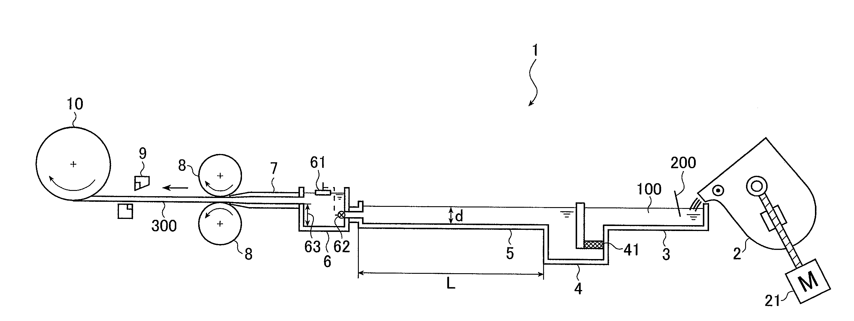
[0147]A continuous cast strip (aluminum alloy strip) 300 was produced using the continuous casting and rolling apparatus 1 shown in FIG. 1.

[0148]A melt 100 prepared in the melting and holding furnace 2 to a composition of 0.3% iron, 0.1% silicon and 0.01% copper, with the balance being inadvertent impurities and aluminum, was poured into a first launder 3. During passage of the melt 100 through the first launder 3, grain refiner wire (diameter, 10 mm) 200 composed of 5% titanium and 1% boron, with the balance being aluminum and inadvertent impurities, was added thereto, bringing the titanium and boron contents within the melt 100 to 0.015% and 0.003%, respectively.

[0149]Degassing treatment was carried out with a degasser (not shown) provided on the first launder 3, and filtration treatment was carried out with a filtering means 4. A ceramic foam filter (thickness, about 50 mm; mesh size, 30 ppi) was used as the filter 41.

[0150]After passing through a second launder 5, a liquid level...

example 2

[0157]Next, the influences of the titanium and boron contents were investigated by carrying out casting at different titanium and boron contents in the melt 100.

[0158]Aside from changing the titanium and boron contents in the melt 100 following addition of the grain refiner wire (diameter, 10 mm) 200 to the three following sets of values, the same procedure was followed as in Example 1. The melt depth D in the second launder 5 was set to 0.15 m.

 (Ti,B)=(0.06%,0.012%)(0.04%,0.01%)(0.025%,0.005%)

[0159]The results are shown in Table 1-2 below.

TABLE 1-2Launder passage time and number of black streaksTi content (%)0.060.040.0250.015B content (%)Passage time t0.0120.010.0050.003(seconds)0.10.150.2 0.25305233191040211595500000600000

[0160]As is apparent from the above results, at higher titanium and boron contents, when the launder passage time t is short, the incidence of black streaks rises. However, black streaks can be kept from arising by having the launder passage time t be longer tha...

examples 3 to 10

, Comparative Examples 1 to 8

[0161]Aside from changing the average flow velocity V (m / s) of the melt 100 in the second launder 5, the width (m) of the second launder 5, the melt depth D (m) in the second launder 5 and the length L of the second launder 5 in the manner shown in Table 3, the same procedure was carried out as in Example 1.

TABLE 3FlowLaunderMeltLaundervelocity Vwidthdepth Dlength LFormulaBlack(m / sec)(m)(m)(m)(2)streaksEX 30.0230.050.10.7satisfied0EX 40.0350.050.11satisfied0EX 50.0460.050.11.3satisfied0EX 60.0690.050.11.9satisfied0EX 70.0120.050.20.7satisfied0EX 80.0170.050.21satisfied0EX 90.0230.050.21.3satisfied0EX 100.0350.050.21.9satisfied0CE 10.0230.050.10.5not satisfied8CE 20.0350.050.10.8not satisfied5CE 30.0460.050.11.1not satisfied5CE 40.0690.050.11.7not satisfied4CE 50.0120.050.20.5not satisfied5CE 60.0170.050.20.8not satisfied3CE 70.0230.050.21.1not satisfied3CE 80.0350.050.21.7not satisfied2


PUM

PropertyMeasurementUnit
thicknessaaaaaaaaaa
thicknessaaaaaaaaaa
sizeaaaaaaaaaa

Abstract

Disclosed is a method of manufacturing, by a continuous casting process, aluminum alloy strip for use in the production of supports for lithographic printing plates, comprising the step of passing an aluminum melt successively through a filtering means, a launder connected to the filtering means, a liquid level controlling means connected to the launder, and a melt feed nozzle connected to the liquid level controlling means, wherein the aluminum melt is obtained by melting an aluminum starting material, then adding to and melting in the molten aluminum starting material a titanium and boron-containing aluminum alloy, and the time t in seconds required for the aluminum melt to pass through the launder satisfies the following condition (1):t≧270×1.2×D ,   (1)where D is the depth in meters of the melt in the launder.The method is able to prevent the formation of black streaks even when casting is carried out for an extended period of time.

Description

BACKGROUND OF THE INVENTION[0001]The present invention relates to a method of manufacturing aluminum alloy strip for use in the production of lithographic printing plates. The invention also relates to an apparatus for manufacturing such aluminum alloy strip. The invention further relates to aluminum alloy strip for use in the production of lithographic printing plates which is obtained by such a method.[0002]Methods of manufacturing aluminum alloy strip for lithographic printing plates by a continuous casting process typically include a casting step which involves melting an aluminum starting material, subjecting the resulting aluminum melt to filtration treatment, feeding the filtered melt via a melt feed nozzle to a pair of cooled rolls, and solidifying and concurrently rolling the aluminum melt by means of the pair of cooled rolls so as to form an aluminum alloy strip; a cold rolling step; an intermediate annealing step; a finish cold-rolling step; and a flatness correcting step...

Claims


Application Information

Patent Timeline
Patent Type & Authority Applications(United States)
IPC IPC(8): B41D3/00C22C21/00
CPCB21B1/463B21B2003/001B22D11/003B22D11/181B22D11/0622B22D11/103B22D11/116B22D11/045
Inventor SAWADA, HIROKAZUUESUGI, AKIO
Owner FUJIFILM CORP
Why Eureka
Try Eureka