
Dental Drilling Assembly

a technology for dental implants and drill bushings, which is applied in dentistry, medical science, dental tools, etc., can solve the problems of affecting the accuracy of dental implants, and difficulty in manipulating drill bushings, so as to prevent contamination of implant sites and accurate drilling

Inactive Publication Date: 2009-01-01
ESPOSTI ALESSIO +1
View PDF8 Cites 48 Cited by
  • Summary
  • Abstract
  • Description
  • Claims
  • Application Information

AI Technical Summary

Benefits of technology

[0008]An advantage of the present invention is that it can overcome at least one of the problems of the prior art devices mentioned above.
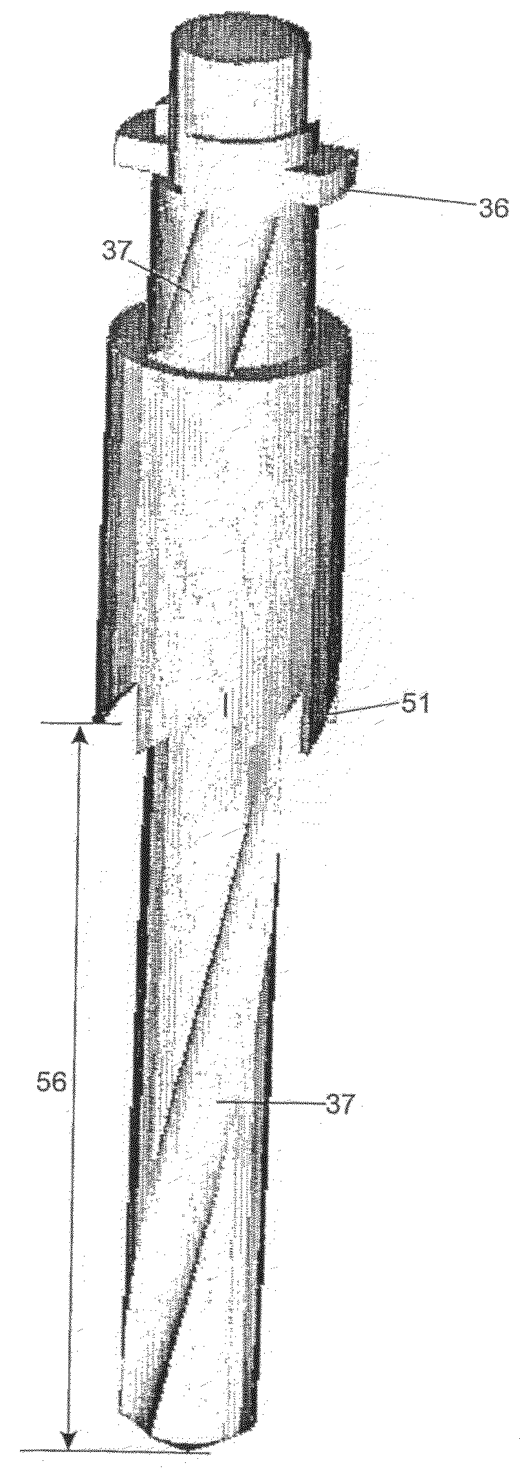
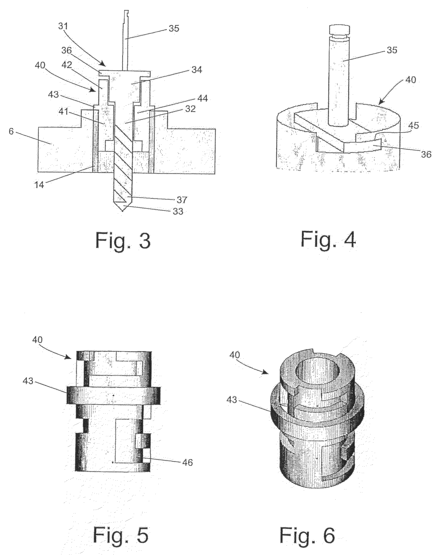
[0009]A first aspect of the present invention provides a dental drilling assembly comprising a drill and a bushing which is mounted, or mountable, coaxially with the drill. By having the bushing mounted, or mountable, to the drill, the bushing can be inserted with the drill into a bore hole of a surgical template and can similarly be removed from the bore hole when a hole has been drilled. This avoids the need to remove the surgical template from the mouth of the patient after drilling operations to remove a bushing from the template. The bushing can be permanently mounted to the drill, or the bushing can be removably mountable to the drill such as by a bayonet or corkscrew type of fixing.
[0010]Preferably, the bushing has at least one cutting surface for cutting soft tissue. The cutting surface can comprise a serrated leading edge of the bushing, a knife-edge or any other suitable form. This has the advantage of avoiding the need to use a separate tissue cutting tool. Such tools may normally require the removal of the surgical template from the patient's mouth.
[0011]Preferably, a pathway is defined between the drill and the bushing which serves, in use, to evacuate soft tissue from the cutting surface. This ensures soft tissue is removed from the cutting site and helps to prevent contamination of the implant site.
[0012]The dental drilling assembly is used in connection with a surgical template having at least one bore hole representing a position where the drill is required to be used, the bore hole having a diameter which accommodates the drill and bushing. Where the bore hole is lined with a bore tube, the bore tube has a diameter which accommodates the drill and bushing. Preferably the bore hole, or bore tube, has a diameter which is only slightly larger than the bushing so that the bushing is accommodated with a sliding fit. This helps to ensure an accurate positioning of the drill at the required drilling site.

Problems solved by technology

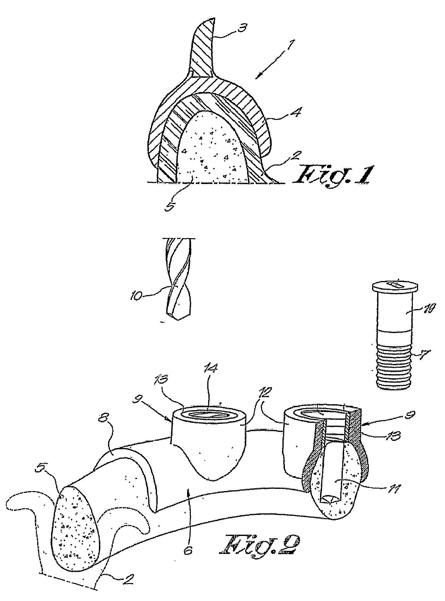
One of the disadvantages of the described method relates to the removal of the drill bushings.
Due to limited space in the mouth of the patient, manipulating the drill bushings is difficult.
An additional problem occurs when the surgical template is fitted directly on the soft tissue or the teeth of the patient.
Indeed when no surgical flap is made the presence of soft tissue overlying the respective implantation sites in the jaw is troublesome.
If the implant cavities are drilled without firstly removing the soft tissue locally, gingival matter can be dragged into the bone cavity and can contaminate the implantation site, eventually leading to implant failure.
This adds further steps to the overall implant process and presents a risk that the template is replaced in a different position in the mouth.

Method used


Image

  • Dental Drilling Assembly
  • Dental Drilling Assembly
  • Dental Drilling Assembly

Examples


Embodiment Construction

[0023]The present invention will be described with respect to particular embodiments and with reference to certain drawings but the invention is not limited thereto but only by the claims. The drawings described are only schematic and are non-limiting. In the drawings, the size of some of the elements may be exaggerated and not drawn on scale for illustrative purposes. Where the term “comprising” is used in the present description and claims, it does not exclude other elements or steps. Furthermore, the terms first, second, third and the like in the description and in the claims, are used for distinguishing between similar elements and not necessarily for describing a sequential or chronological order. It is to be understood that the terms so used are interchangeable under appropriate circumstances and that the embodiments of the invention described herein are capable of operation in other sequences than described or illustrated herein.

[0024]Before describing the drilling assembly i...


PUM


Abstract

A dental drilling assembly comprises a drill (30) and a bushing (40) which is mounted, or mountable, coaxially with the drill (30). The bushing (40) can be inserted with the drill (30) into a bore hole of a surgical template and can similarly be removed from the bore hole when a hole has been drilled. The bushing has a serrated leading edge (51) for cutting soft gingival tissue. A pathway (54, 55) is defined between the drill (30) and the bushing (40). The pathway (54, 55) cooperates with a fluted channel on the drill and serves, in use, to evacuate soft tissue from the cutting surface (51). A surgical template has at least one bore hole representing a position where the drill is required to be used. The bore hole, or a bore tube lining the bore hole, has a diameter which is only slightly larger than the bushing.

Description

FIELD OF THE INVENTION[0001]This invention relates to a dental drilling assembly which can be used to drill holes in the bone of a patient for the fitting of dental implants as well as a method of manufacture of and using the assembly.BACKGROUND TO THE INVENTION[0002]In dental treatment methods and devices are known for determining the ideal placement of an implant. Such treatment methods typically consist of a number of steps. Firstly a diagnostic wax-up is created to represent the desired prosthetic end result. The wax-up is optimized to achieve proper occlusion, morphology, aesthetics and phonetics. Next, a scanning template or scan prosthesis is manufactured. This is a replica of the wax-up made in a radio-opaque material to ensure that it is clearly visible in the medical images when the patient is scanned.[0003]Following production of the scan template, the patient is sent to a radiologist for scanning (CT, MRI or the like). The output of the scan is a stack of 2D slices formi...

Claims


Application Information

Patent Timeline
Patent Type & Authority Applications(United States)
IPC IPC(8): A61C3/02
CPCA61B17/1637A61B17/1673A61C8/0089A61B2019/304A61C1/082A61B17/176A61B2090/034A61C1/084
Inventor ESPOSTI, ALESSIOVAN LIERDE, CARL
Owner ESPOSTI ALESSIO
Learn More