Control apparatus for internal combustion engine and control method therefor

a control apparatus and internal combustion engine technology, applied in combustion engines, valve arrangements, machines/engines, etc., can solve the problems of insufficient reduction of pumping loss, insufficient improvement of fuel economy performance, and largely worsening of fuel economy, so as to enhance the torque of output engines, increase intake air quantity, and improve fuel economy.

Inactive Publication Date: 2009-01-08
HITACHI LTD
View PDF15 Cites 25 Cited by
  • Summary
  • Abstract
  • Description
  • Claims
  • Application Information

AI Technical Summary

Benefits of technology

[0007]Because the fact that a variation of number of working cylinders results in a remarkable change in an intake air quantity is needed to be absorbed by a large variation of the opening angle (quantity) of the opening angle variable of the engine throttle valve. Therefore, during the all cylinder driving region in which the opening angle variable of the engine throttle valve is controlled to be small (narrow), a pumping loss due to a negative pressure within an intake manifold of the engine is easy to be developed and, consequently, the fuel economy becomes largely worsened.
[0008]In addition, when the engine driving region is transferred to the partial cylinder halt driving region, in order to enhance an output engine torque by means of the working cylinders, the opening angle (quantity) of the engine throttle valve is controlled to be relatively large to increase the intake air quantity per cylinder, thus suppressing the development of the torque stepwise difference.

Problems solved by technology

Therefore, during the all cylinder driving region in which the opening angle variable of the engine throttle valve is controlled to be small (narrow), a pumping loss due to a negative pressure within an intake manifold of the engine is easy to be developed and, consequently, the fuel economy becomes largely worsened.
Therefore, the pumping loss cannot sufficiently be reduced and it may be thought that, even under this driving state, the fuel economy performance cannot sufficiently be improved.

Method used


Image

  • Control apparatus for internal combustion engine and control method therefor
  • Control apparatus for internal combustion engine and control method therefor
  • Control apparatus for internal combustion engine and control method therefor

Examples


first embodiment

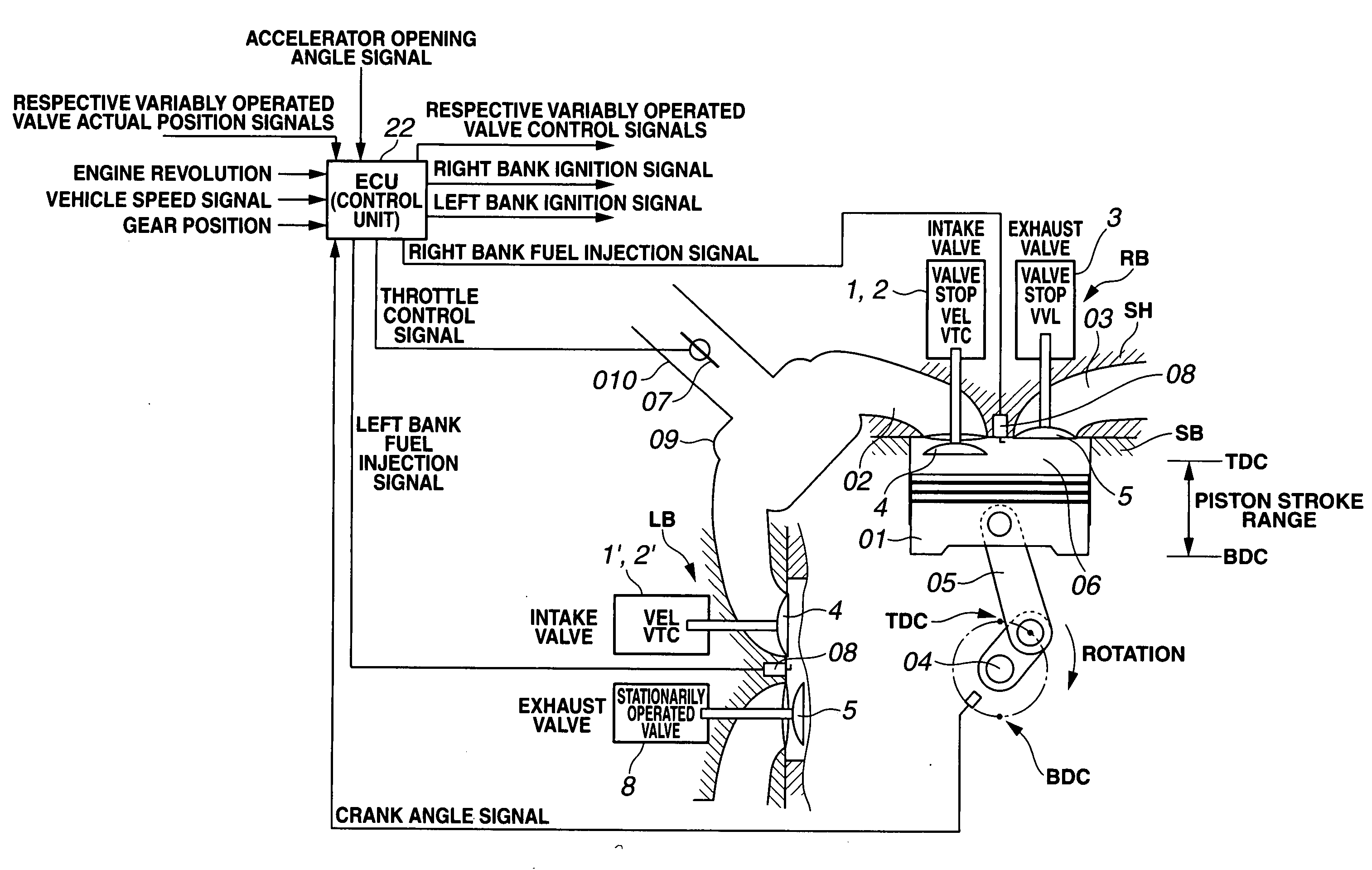
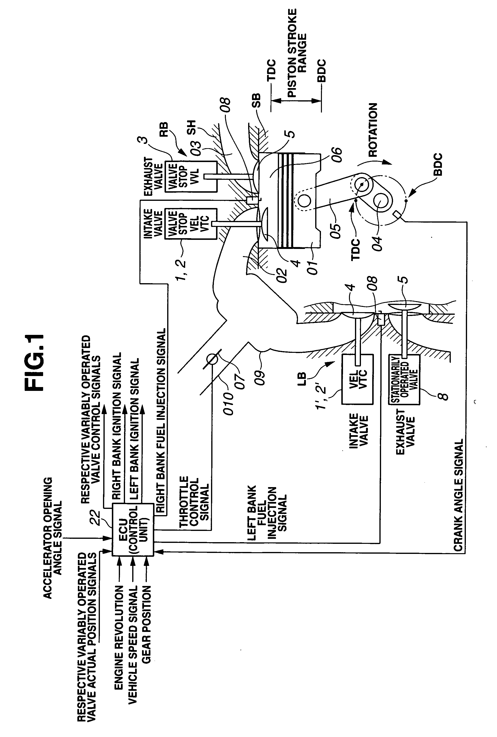
[0033]An outline of a whole structure of the V-type internal combustion engine will be described on a basis of FIG. 1. While a three-cylinder right bank RB which corresponds to a first cylinder group and provides a (operation) halt enabled cylinder group, a three-cylinder left bank LB which corresponds to a second cylinder group and provides an operation enabled cylinder group working at all times.

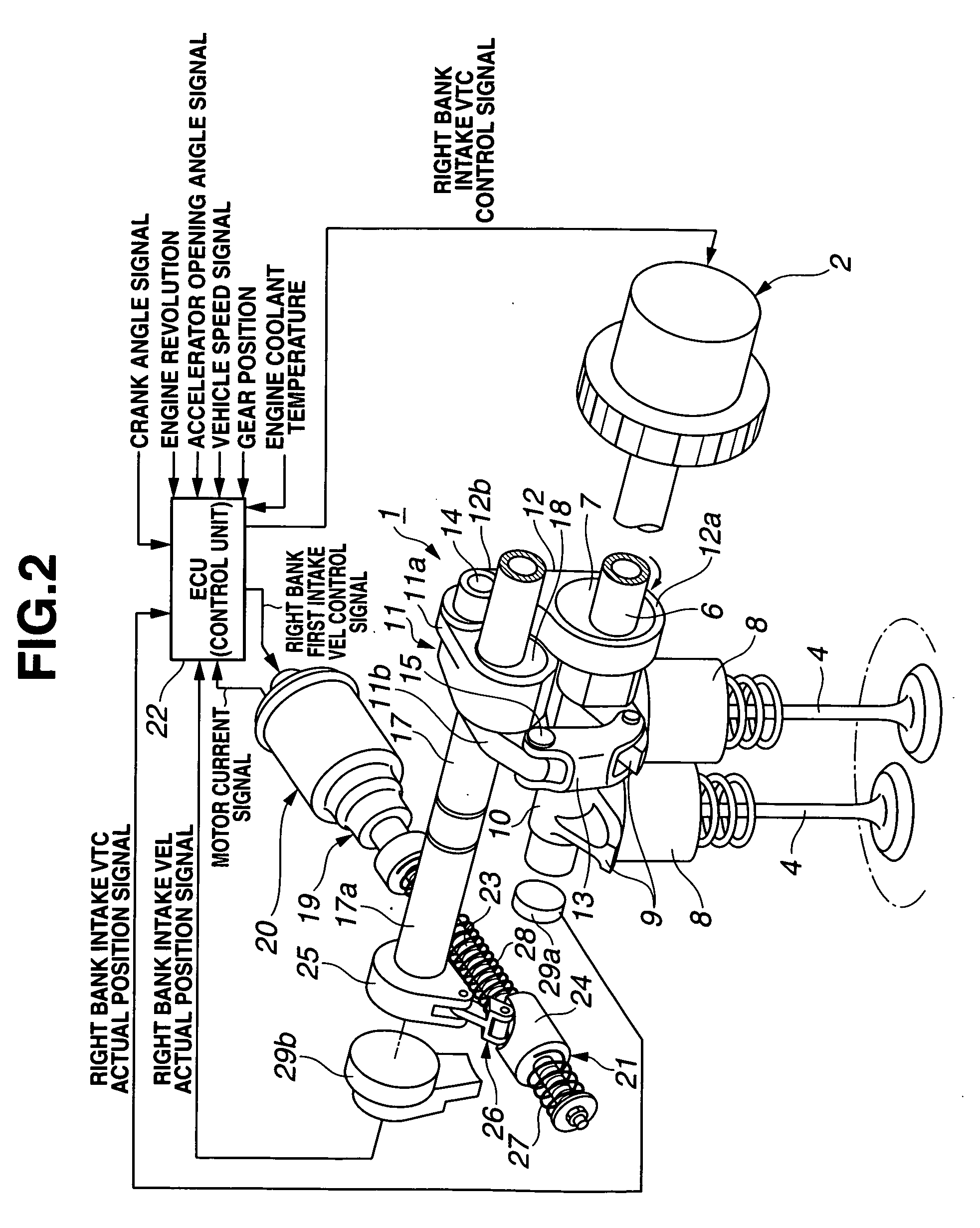
[0034]In addition, the internal combustion engine shown in FIG. 1 includes two intake valves 4, 4 and exhaust valves 5, 5 for the respective cylinders. Right bank RB includes: a first intake VEL (Valve Event and Lift) 1 which is an intake side lift (quantity) variable mechanism used to variably control a valve lift (quantity) of intake valves 4, 4 of each of the cylinders of the right bank; a first intake VTC (Variable Timing Control) 2 which is an intake side lift-and-phase variable mechanism used to variably control valve-open-and-closure timings of intake valves 4, 4 of each of the cyli...

second embodiment

[0101]FIGS. 11 through 13 show control characteristics by the control apparatus in a second preferred embodiment according to the present invention. As shown by a control map of FIG. 11, in all cylinder driving region A during the light load driving including an idling (state) driving, a lean burn control such that air mixture fuel whose fuel is injected from each of fuel injection valves 08 of left and right banks LB, RB to corresponding combustion chamber 06 is more dilute than a stoichiometric air-fuel ratio is carried out. According to the lean burn control, the engine torque with respect to the same intake air volume is reduced. To obtain a target torque, the lift (quantity) is needed to be made large.

[0102]Herein, the boundary of mutually adjacent driving regions and the proximity to the boundary when the swept engine driving condition is transferred from all cylinder driving region A to reduced cylinder driving region B will be described below. When the driving region is tran...

third embodiment

[0110]FIGS. 14 and 15 show control characteristics by the control apparatus in a third preferred embodiment according to the present invention. In this embodiment, as shown in a control map of FIG. 14, first and second hysterisises of mutually the same characteristics are provided for a switching boundary line between the valve stop and the valve lift operation in intake valves 4, 4 of right bank RB and for a switching boundary line of a lift abrupt change line of intake valves 4, 4 of both of left bank LB and right bank RB.

[0111]That is to say, a switching line E in an engine-load-and-engine-revolution decreasing direction between all cylinder driving region A and reduced cylinder driving region B with respect to another switching line Ed in an engine-load-and-engine-revolution increasing direction is slightly set in the engine-load-and-engine-revolution decreasing direction, as shown in FIG. 14. In other words, first hysterisis of a width of ΔE is provided as shown in FIGS. 14 and...


PUM


Abstract

In control apparatus and method for an internal combustion engine, a first cylinder group in which both of intake and exhaust valves of each of engine cylinders thereof are controllably stopped is provided, second cylinder group in which a lift of the intake valve of each of the engine cylinders thereof is variably controlled is provided, and the lift of the intake valve of each of the engine cylinders of the second cylinder group is controlled n order for an engine torque when the intake and exhaust valves of each of the cylinders of the first cylinder group are controlled to be stopped to be approximately equal to the engine torque by means of the first cylinder group and the second cylinder group before the intake and exhaust valves of each of the cylinders of the first cylinder group are controlled to be stopped.

Description

BACKGROUND OF THE INVENTION[0001](1) Field of the Invention[0002]The present invention relates generally to a control apparatus for an internal combustion engine and a control method therefor. The present invention relates particularly to the control apparatus for the internal combustion engine and the control method therefor which are capable of improving a fuel economy and capable of suppressing a torque shock to be developed when an engine driving region is transferred to a partial cylinder halt (reduced cylinder) driving region in which operations of intake and exhaust valves of a given part of cylinders of the engine mounted in an automotive vehicle are temporarily stopped (stopped in closed states) (so-called, a cylinder halt).[0003](2) Description of Related Art[0004]A Japanese Patent Application Publication No. Heisei 10-82334 published on Mar. 31, 1998 exemplifies a previously proposed engine control apparatus which can perform the cylinder halt described above. In the abov...

Claims


Application Information

Patent Timeline
Patent Type & Authority Applications(United States)
IPC IPC(8): F01L1/34
CPCF01L1/267F01L13/0005F01L13/0026Y02T10/18F01L2013/0073F02D13/06F01L13/0036Y02T10/12
Inventor NAKAMURA, MAKOTO
Owner HITACHI LTD
Why Eureka
Try Eureka