Flexible silo apparatus having a top removable valve or flow control device

a flexible silo and valve technology, applied in the field of flexible silo or bulk bag apparatus, can solve the problems of unreliable product flow from such containers, vibration can contribute to unreliable or no-flow conditions, and blended products become unblended

Inactive Publication Date: 2009-01-08
KOSICH MARK MICHAEL
View PDF2 Cites 24 Cited by
  • Summary
  • Abstract
  • Description
  • Claims
  • Application Information

AI Technical Summary

Problems solved by technology

It is also known that product flow from such containers can be unreliable.
And it is known that vibration can also contribute to unreliable or no-flow conditions when used with certain products by de-aerating and compacting the product.
Filling powder or granular product into rigid storage containers often results in blended products becoming unblended and fragile products can be damaged.
This results from the free-fall and velocity of product descending from upstream equipment through the empty volume of the container and onto the bottom of the container.
Therefore, displaced air containing airborne product exits the container and is lost to the atmosphere or must be contained and separated using a dust collection system.
Connecting or removing the valve or flow control device must be done from the underneath since no practical provision is made to load the valve from above and rest it upon a support bridge at the bin outlet.
Flexible silo materials sometimes used but are not generally conducive to washing and sterilization and are not widely used in wash down applications but instead can be replaced and discarded.
This may also require an apparatus to receive and support the valve since it is awkward to handle a valve in such a position.
This also increases the need for more robust heavy duty flexible silo fabric and seam construction which leads to higher flexible silo cost.
Air injected into a container to facilitate product flow must be evacuated, thereby, resulting in additional pollution control equipment and loss of product.
This approach requires airtight materials and seam construction and very heavy duty fabric...

Method used


Image

  • Flexible silo apparatus having a top removable valve or flow control device
  • Flexible silo apparatus having a top removable valve or flow control device
  • Flexible silo apparatus having a top removable valve or flow control device

Examples


Embodiment Construction

[0066]A detailed description of the invention is provided herein. It is to be understood, however, that the present invention may be embodied in various forms. Therefore, specific details disclosed herein are not to be interpreted as limiting, but rather as a basis for the claims and as a representative basis for teaching one skilled in the art to employ the present invention in virtually any appropriately detailed system, structure or manner.

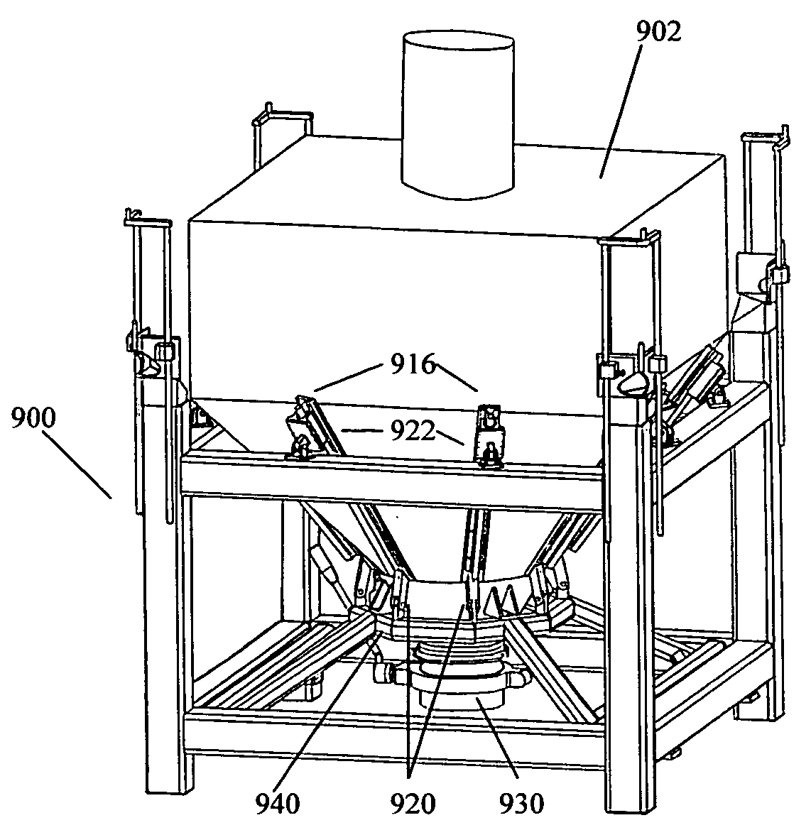
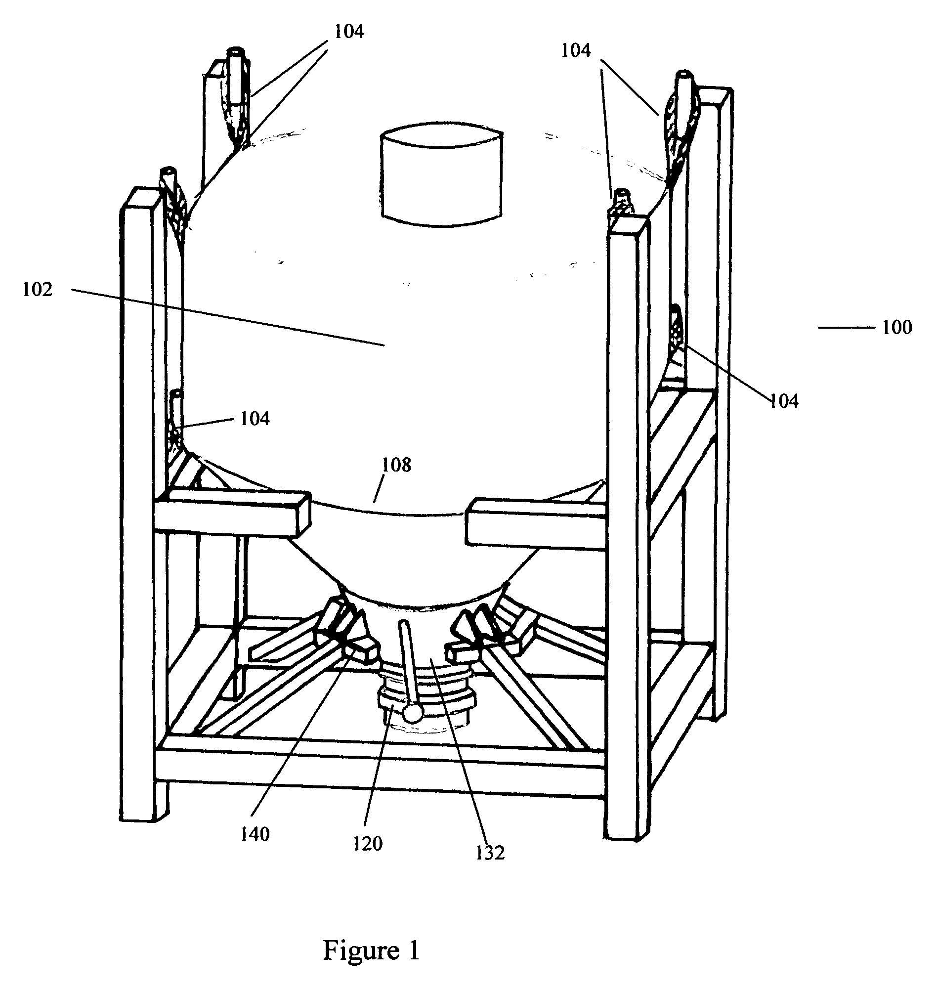
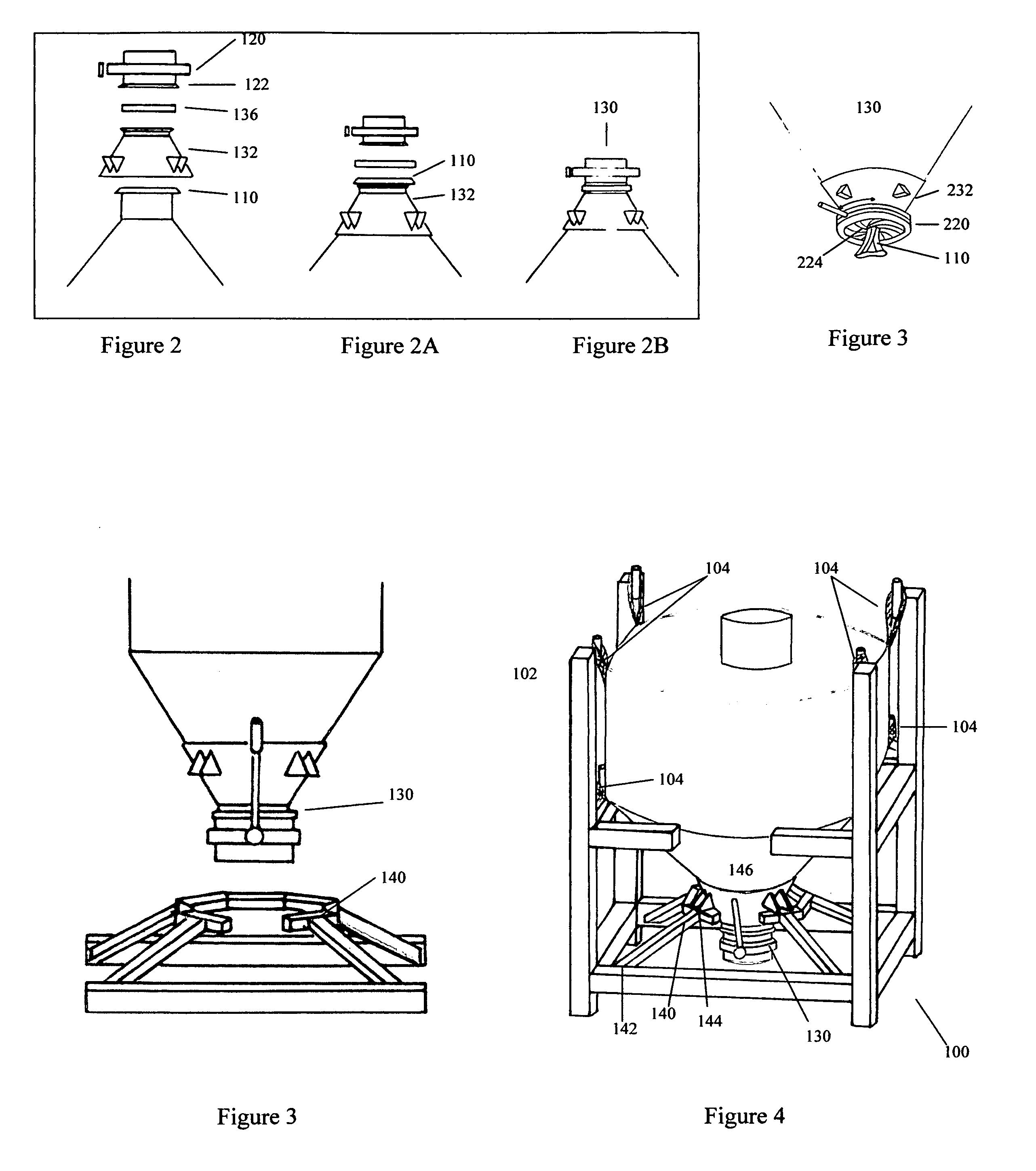
[0067]Turning first to FIG. 1, a preferred embodiment of the invention is shown having a support structure 100 constructed of a plurality of members to support a flexible silo. The length, height and width of the support structure 100 is in proportion to the dimensions of the flexible silo 102 that is supported upon the structure by connectors 104 located on flexible silo 102. Connectors 102 are typically recognized as, yet not limited to, loops or sleeves by one skilled in the art. For illustrative purposes, this detailed description will show...


PUM


Abstract

A flexible silo apparatus having a top removable valve or flow control device assembly has a top removable valve or flow control device that has components to interface with the outlet of a flexible container and that can be supported upon a bridge. Various cone configurations can be added to support the cone section or bottom of a flexible container including a rigid cone, multi member cone, or “y Axis dynamic cone system. The apparatus is further enhanced with a floating bridge and the addition of a powered lifting and lowering device for the advantage of manipulating the flexible container in a vertical motion for improving the filling of product into or the discharging of product out of a flexible container.

Description

BACKGROUND OF THE INVENTION[0001]This invention relates generally to the field of bulk material handling and more specifically to a flexible silo or bulk bag apparatus.Silos, Hopper, Day Bind and Portable Bins[0002]Silos, bins, hoppers, day bins and portable bins are presently known for use as rigid storage containers for powder and granular product comprising a cone section with an outlet and using a wide variety of valves or flow control devices that can be used to control product flow. A vertical straight side section above the cone section increases the storage capacity. These storage systems are usually constructed with a storage container body made of steel, aluminum or plastic and have a support structure usually constructed of steel or aluminum and sometimes rigid plastic.[0003]It is also known that product flow from such containers can be unreliable. Brute force equipment such as a mechanical agitator, pulsing cone valve or air injector devices can be installed inside the s...

Claims


Application Information

Patent Timeline
IPC IPC(8): B65D35/56B65D88/54
CPCB65D88/1668B65D90/56B65D90/205B65B69/0091
Inventor KOSICH, MARK MICHAEL
Owner KOSICH MARK MICHAEL
Why Eureka
Try Eureka