
Content discharge mechanism for pump-type container and pump-type product with content discharge mechanism

a technology of content discharge mechanism and pump-type container, which is applied in the direction of pliable tubular containers, liquid transferring devices, single-unit apparatuses, etc., can solve the problems of complex structure of the entire structure, uneven flow of chemical fluids, and gradual reduction of the pressure of chemical fluids in the space [a] in the discharge mode, etc., to suppress the change in the properties of contents.

Active Publication Date: 2009-01-08
MITANI VALVE CORP
View PDF10 Cites 27 Cited by
  • Summary
  • Abstract
  • Description
  • Claims
  • Application Information

AI Technical Summary

Benefits of technology

[0026]In accordance with the present invention, the discharge valve of a pump type product is provided on the downstream passage communicated with the upstream passage to extend to the fixed type content discharge outlet, not on the upstream passage located between the suction valve and the piston interlocking with the operation part, so that the content discharge outlet is maintained at the stationary mode position before the operation even when the operation part is moved upon setting operation to the discharge mode, resulting in a convenient mechanism making the pump mechanism itself simple for a smooth flow of the contents therein.
[0027]The mechanism is configured such that the discharge valve of the downstream passage is made a pressure storage type, and when the operation part is moved by a predetermined stroke i.e. a sealing action part off the piston for specifying the upstream passage advances to a facing position of the communication hole (between the upstream passage and the downstream passage) while abutting a cylinder inner peripheral surface, a cylinder space region separated from the content passage up to just before is communicated with the upstream passage and the downstream passage after passage through the hole to permit the pressure of the contents to the discharge valve to be abruptly reduced, so that opening and closing operation of the discharge valve, so that the opening and closing operation of the discharge valve are made quick, ensuring the “sharpness” of each operation at the time of starting or finishing of the discharge of the contents of the discharge valve.
[0028]The first elastic member for energizing the operation part and the piston integral therewith to the stationary mode position and the second elastic member for energizing the discharge valve to a closed state are disposed outside the passage of the contents, and the suction valve is made of a synthetic resin and there is no chance of the metal part of the component of the content discharge mechanism making contact with the contents, so that it is possible to suppress a change in properties of the contents following the contact and performance deterioration of the mechanism itself.

Problems solved by technology

The foregoing content discharge mechanism suffers from the problem that not only the suction valve but also the discharge valve are formed with the large piston [23] and the small piston [22] provided on the vertical upstream passage i.e. the downstream passage up to the nozzle hole [16a1] extending to the upstream passage does not include the valve member so that the entire structure is complicated and a flow of the chemical is not smooth.
Further, pressure of the chemical in the space [B] in the discharge mode is gradually reduced, so that injection finishing operation of the chemical (transition operation from the discharge mode to the discharge finishing mode) lacks sharpness.

Method used


Image

  • Content discharge mechanism for pump-type container and pump-type product with content discharge mechanism
  • Content discharge mechanism for pump-type container and pump-type product with content discharge mechanism
  • Content discharge mechanism for pump-type container and pump-type product with content discharge mechanism

Examples


embodiment 1

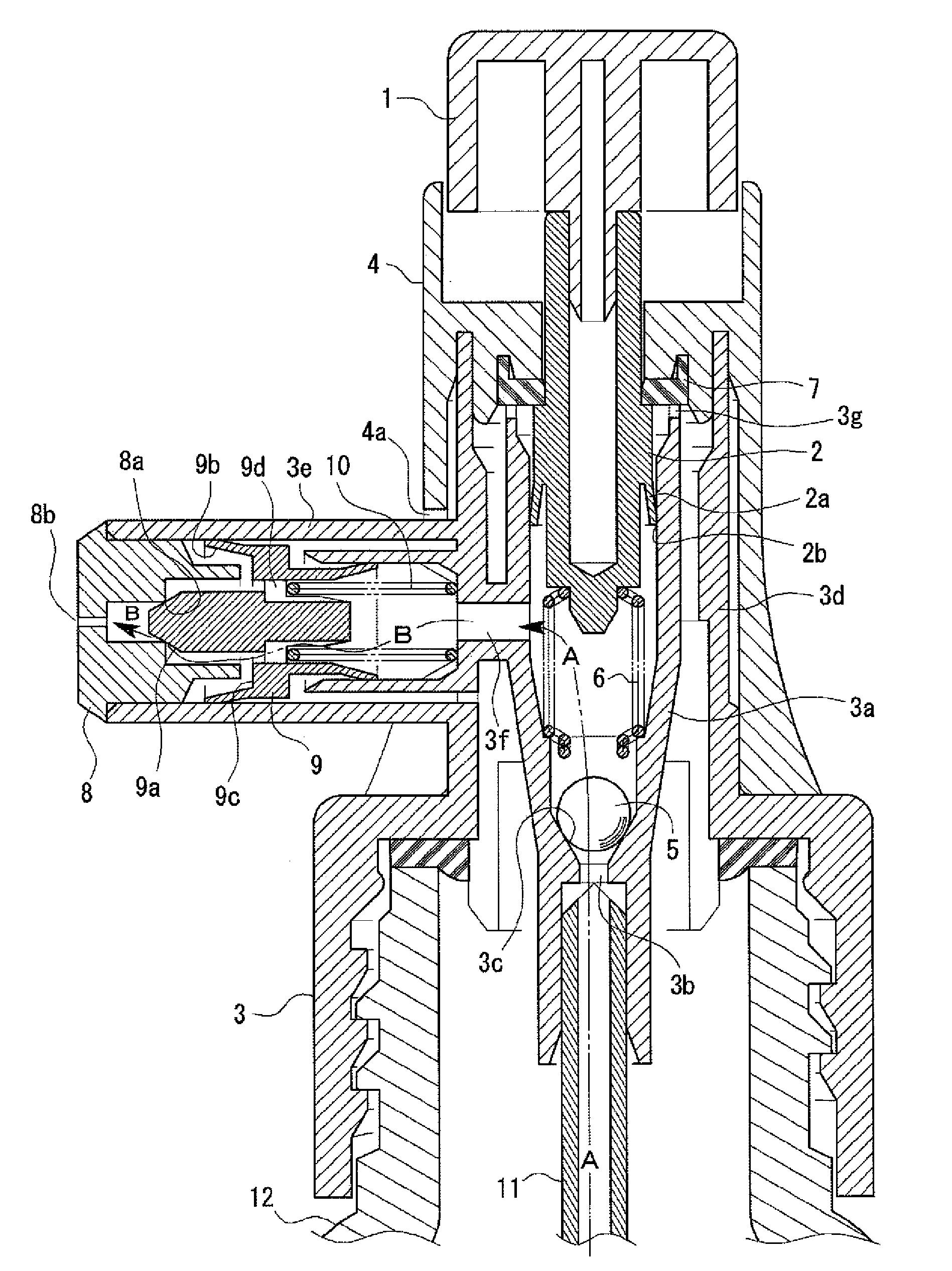
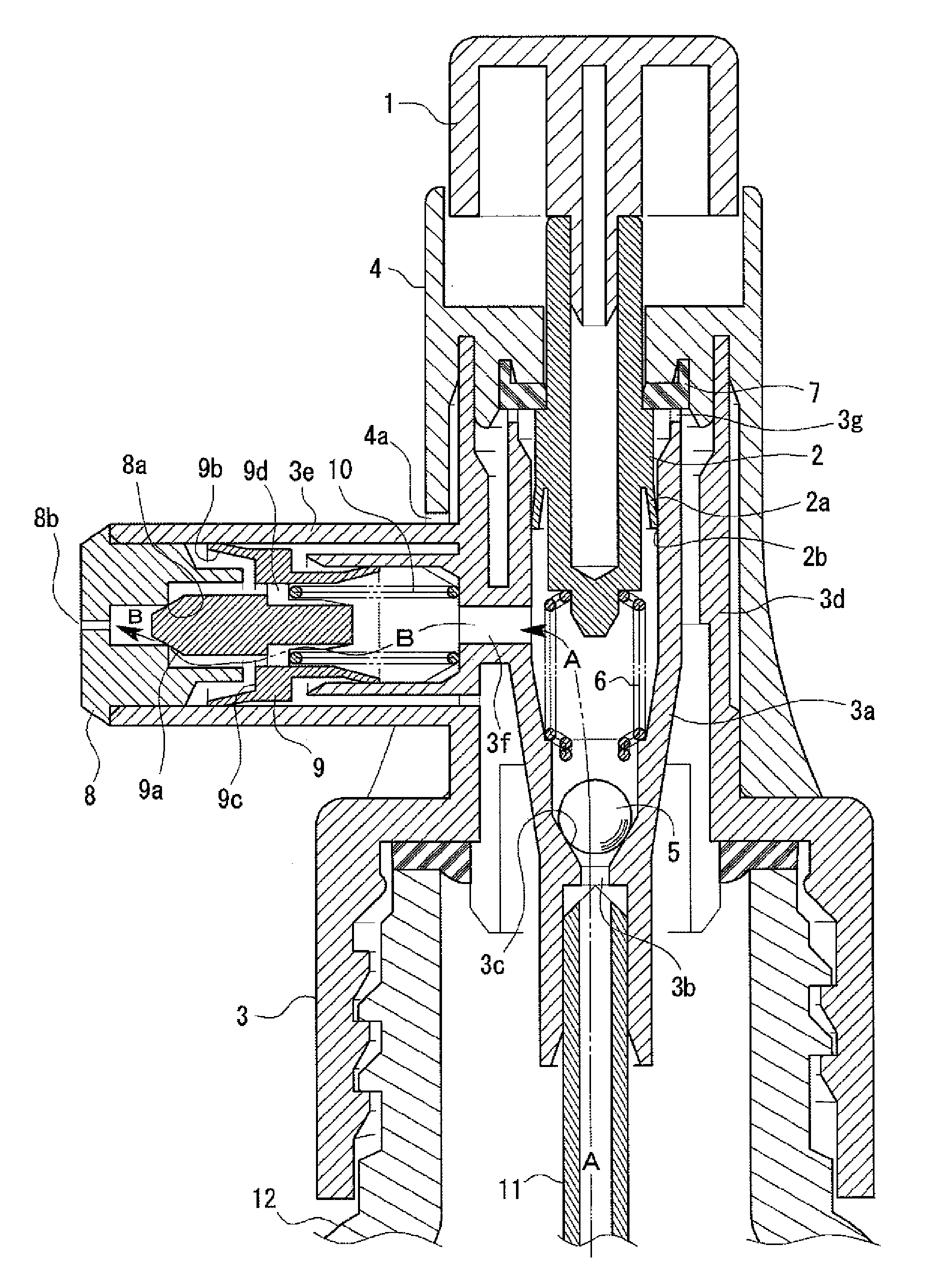
[0218]In the stationary mode in FIG. 1,

(1a) the operation button 1 and the sheath-shaped piston 2 move upward by the action of the coil spring 6,

(1b) the suction valve and the discharge valve are closed, and

(1c) the contents enter the upstream passage A and the downstream passage B (part thereof) extending from the suction valve (at least after a pump type product is used even one time) via the hole 3f for communication to the discharge valve.

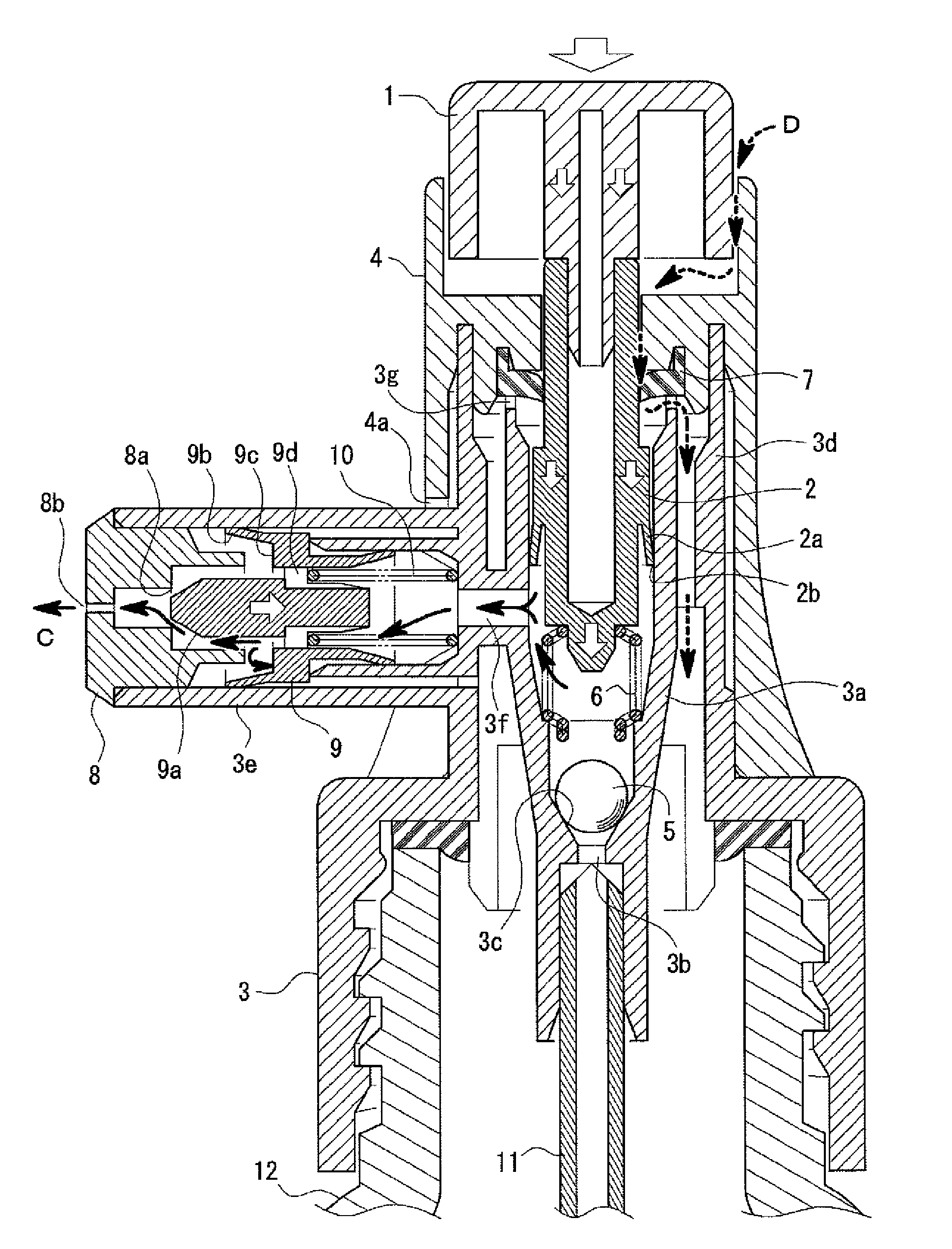
[0219]In the discharge mode in FIG. 2 where the sealing action part 2b of the sheath-shaped piston 2 is yet located at an upward position from the hole 3f for communication by depressing the operation button 1,

(1d) in response to lower movement of the sheath-shaped piston 2a a volume of the passage of (1c) is reduced to gradually raise content pressure there,

(1e) when the total pressure of the contents in the right direction in the figure received by the annular flat surface 9c or the like becomes stronger than driving force to the left directi...

embodiment 2

[0228]A content discharge mechanism in FIG. 4 is basically different from that of FIG. 1 as follows:

(21) A rotary type operation lever (trigger lever) is employed instead of the operation type 1 of depression type.

(22) When turning operation of the trigger lever in an illustrated clockwise direction of the trigger lever (discharge mode setting operation) is performed, there are provided a lateral sheath-shaped piston interlocking with the trigger lever and a coil spring for energizing the piston in the illustrated right direction (stationary mode position).

(23) As the discharge member on which the output side piece 8 is mounted there is provided a lateral nozzle member independent from the screw cap in FIG. 1.

(24) A restriction piece is formed on the cap for restricting the amount of upward movement of the spherical body 5.

[0229]In the stationary mode in FIG. 4,

(2a) the sheath-shaped piston 22 moves in the illustrated right direction owing to the action of the coil spring 26, and th...

embodiment 3

[0238]The content discharge mechanism in FIG. 5 is basically different from that in FIG. 4 as follows:

(31) a longitudinal nozzle member is used instead of the lateral nozzle member 24 in FIG. 4;

(32) a piston 9 presenting discharge valve action between it and the longitudinal nozzle member and a coil spring 10 for energizing the piston upward are provided vertically; and

(33) the whole of the upstream passage A and downstream passage B are made substantially vertically linear.

[0239]In the stationary mode in FIG. 5,

(3a) the sheath-shaped piston 22 is moved in the illustrated right direction by the action of the coil spring 26 and the operation lever 21 interlocking via the sheath-shaped piston and the rib-shaped part 21b is in an initial state where it is turned anticlockwise;

(3b) the suction valve and the discharge valve are closed;

(3c) the contents are contained in the upstream passage A and the downstream passage B (part thereof) extending from the suction valve (after a pump type p...


PUM


Abstract

A content discharge mechanism of a pump type container, which prevents the position of a content discharge outlet from moving following discharge operation is disclosed. The mechanism includes an operation button 1; a sheath-shaped piston 2 interlocking with the operation button 1; a suction valve including annular reception surface 3c and spherical body 5 actuated in response to the movement of the sheath-shaped piston 2; an upstream passage A formed between the sheath-shaped piston 2 and the suction valve; a downstream passage B communicated with the upstream passage A and formed between it and a discharge outlet 8b; and a pressure storage type discharge valve including annular edge part 8a and annular tapered surface 9a. In a discharge finishing mode, the pressure in the contents is lowered by permitting the downstream side passage B to be communicated with a passage outside space region E via a hole 3f, to close the discharge valve.

Description

TECHNICAL FIELD[0001]The present invention relates to a content discharge mechanism of a pump type container and more particularly, to a content discharge mechanism capable of preventing the position of a content discharge outlet from moving in response to an operation part upon setting operation of a discharge mode of a pump type product, and of making sharp a content discharge starting operation and a content discharge finishing operation by making the mechanism one where a discharge valve on the side of the discharge outlet is surely changed over from an open state (=discharge mode) up to that time to a closed state (=discharge finish mode) when a content discharge outlet portion is settled in the form of a fixed member not moving even in actuation of an operation part, a pressure storage type is used for the discharge valve, and the operation section moves by a predetermined stroke following a setting operation of the content to the discharge mode.[0002]The content discharge mec...

Claims


Application Information

Patent Timeline
IPC IPC(8): B67D5/42B67D7/60
CPCB05B11/0018B05B11/3016B05B11/3015B05B11/3011B05B11/00442B05B11/0067B05B11/0032B05B11/0027B05B11/1016B05B11/1015B05B11/104B05B11/1011B05B11/0039
Inventor OHSHIMA, YASUO
Owner MITANI VALVE CORP
Learn More