Heating device, reflow device, heating method, and bump forming method

a technology of heating method and reflow device, which is applied in the direction of non-electric welding apparatus, drying solid materials, drying machines, etc., can solve the problems of difficult to form desired bumps on the substrate, inability to form proper bumps, and oxidized solvent paste on the substrate, etc., to suppress the influence of bubbles, reduce the evaporation of organic acid, and suppress the effect of organic acid evaporation

Active Publication Date: 2009-01-08
TAMURA KK
View PDF11 Cites 7 Cited by
  • Summary
  • Abstract
  • Description
  • Claims
  • Application Information

AI Technical Summary

Benefits of technology

[0109]Regarding the lid structure 51 according the a ninth embodiment, the inside space 51g formed inside the inner lid 51d is kept to a pressured state. Thus, the boiling point of an organic acid (breakdown product) contained in the liquid-state substance of a solder composition 10 within a container 30 becomes high, which has an effect of decreasing evaporation of the organic acid within the solder composition 10. Through this, generation of bubbles within the liquid-state substance in the heated solder composition 10 can be suppressed. Therefore, when the solder fine particles precipitate in the liquid-state substance, the influence of the bubbles can be suppressed as much as possible so as to form stable bumps. Further, through pressurization, it becomes possible t...

Problems solved by technology

However, the reflow device according to the conventional case 3 heats the substrate by applying the hot air from the top and bottom of the substrate, so that the solder paste on the substrate is oxidized due to an infl...

Method used


Image

  • Heating device, reflow device, heating method, and bump forming method
  • Heating device, reflow device, heating method, and bump forming method
  • Heating device, reflow device, heating method, and bump forming method

Examples


first embodiment

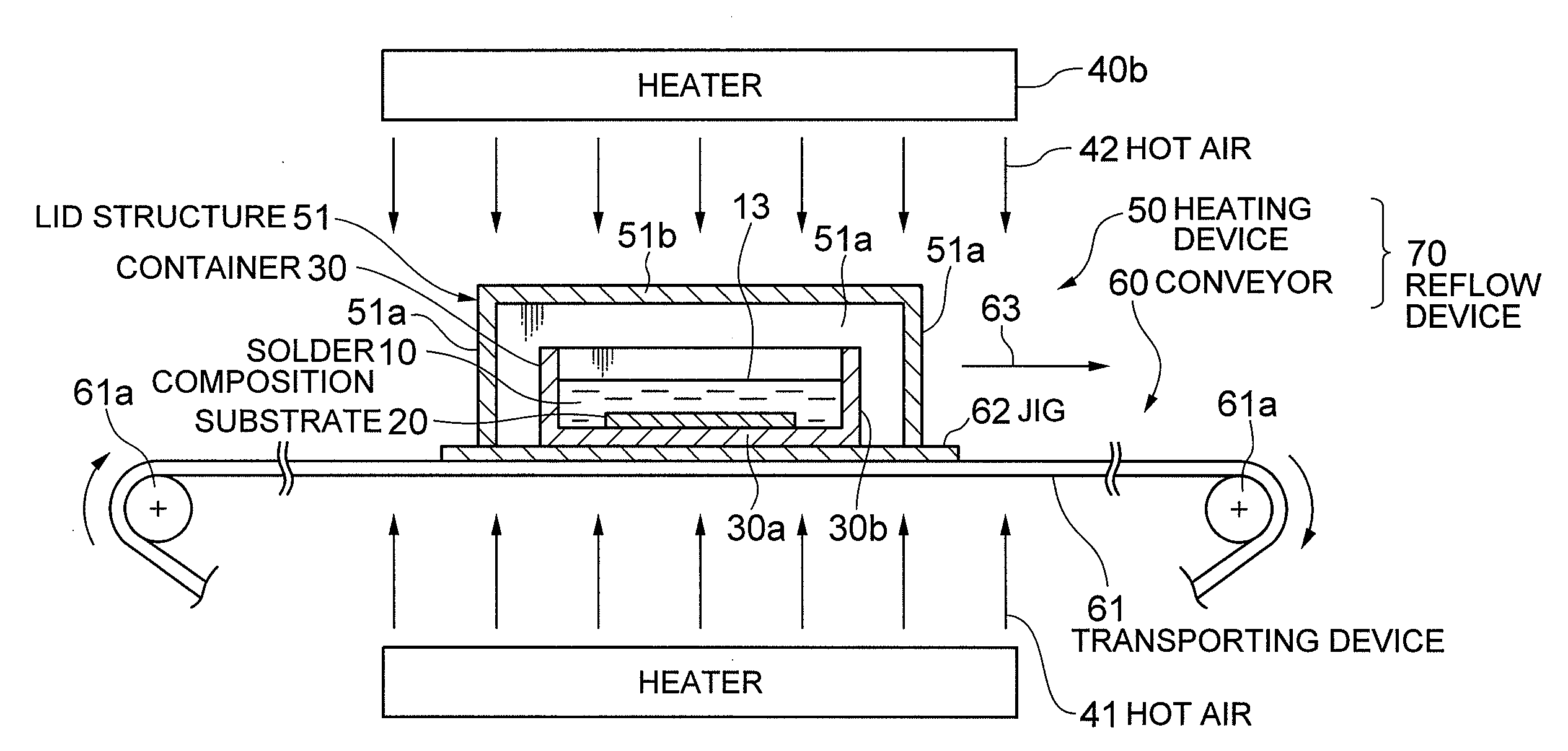
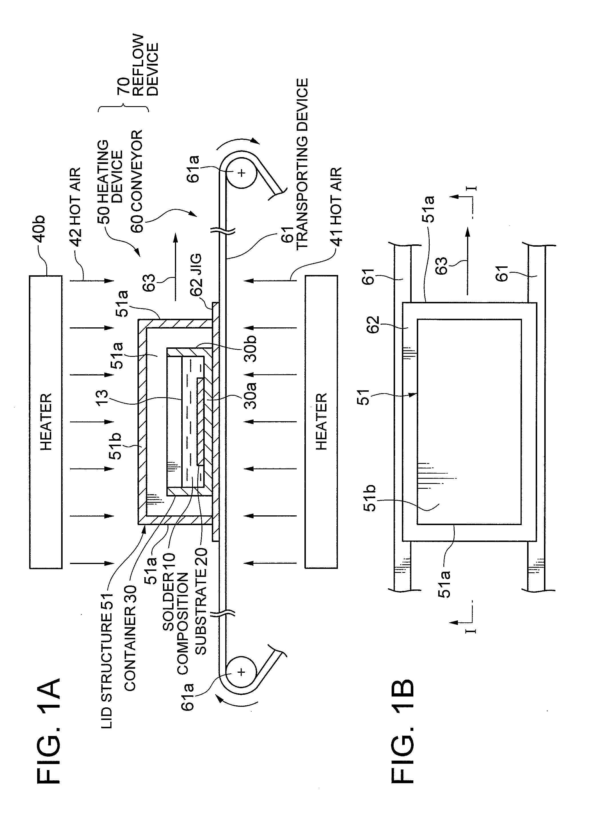
[0026]A heating device for heating a heat-target including a solder composition with hot air will be described as a first embodiment of the present invention. In the drawings, the perpendicular direction is enlarged than the actual scales compared to the horizontal direction for convenience' sake.

[0027]As a basic structure, a heating device 50 according to the first embodiment of the present invention comprises a heater for heating the heat-target including the solder composition with hot air, which is further provided with a hot-air suppressing device 51. The hot-air suppressing device 51 has a function of suppressing a contact between the hot air and the heat-target, and the hot-air suppressing device 51 according to the first embodiment shown in FIGS. 1A and B is formed as a lid structure that covers the heat-target. Next, the hot-air suppressing device 51 shown in FIGS. 1A and 1B will be described.

[0028]The hot-air suppressing device 51 according to the first embodiment shown in...

second embodiment

[0081]A modification example of the heating device according to the first embodiment of the present invention will be described as a second embodiment.

[0082]A heating device 50a according to the second embodiment of the present invention shown in FIG. 6 is characterized to provide a mechanism to a lid structure 51 for keeping the space where a heat-target is covered by the lid structure 51 to a low-oxygen atmosphere. That is, the lid structure 51 is provided with valves 52 and 53 which seal and keep a nitrogen gas N2 within the space inside the lid structure 51. Further, sealing members 71 such as rubbers for increasing the sealing property are attached to an end face 54 of the lid structure 51 that comes in contact with a jig 62.

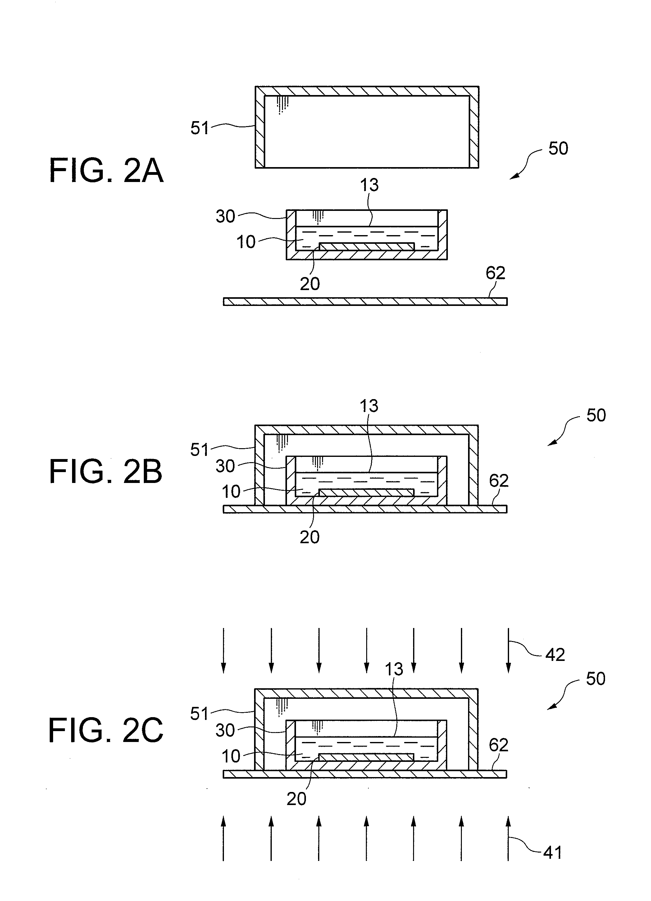
[0083]Next, a heating method using the heating device 50a shown in FIG. 6A will be described. First, as shown in FIG. 6B, a solder composition 10 and a substrate 20 are placed in a container 30, the container 30 is loaded on the jig 62, and the container 30...

third embodiment

[0085]FIG. 7 shows sectional views showing a heating device according to a third embodiment of the present invention, and heating step is executed in order of FIGS. 7A, 7B, and 7C. Explanations will be provided hereinafter by referring to the drawings. However, same reference numerals are applied to the same components as those of FIG. 2, and explanations thereof will be omitted.

[0086]In a heating device 50b according to the third embodiment of the present invention shown in FIG. 7, a lid structure 51 is provided with a mechanism for keeping the space covered by the lid structure 51 to a negative-pressure atmosphere. That is, the lid structure 51 is provided with a valve 52 which keeps the space inside the lid structure 51 to be under a negative pressure. Further, sealing members 71 such as rubbers for increasing the sealing property are attached to an end face 54 of the lid structure 51 that comes in contact with a jig 62.

[0087]Next, a heating method using the heating device 50b wi...


PUM

PropertyMeasurementUnit
Temperatureaaaaaaaaaa
Pressureaaaaaaaaaa
Heataaaaaaaaaa

Abstract

A solder bump is formed on a substrate by using a heating device where a lid structure blocks hot air from directly blowing against a solder composition. The heating device can reduce high-temperature oxygen molecules that come into contact with the solder composition, oxidation of the solder composition is suppressed. As a result, although the hot air is used for heating, a solder bump can be formed by the liquid-like solder composition. Further, because the lid structure is uniformly heated by the hot air, radiation heat from the lid structure is also uniform, and a container is more uniformly heated. In addition, because the hot air is suppressed from directly blowing against a liquid surface, the liquid-like solder composition is not scattered by the hot air.

Description

TECHNICAL FIELD[0001]The present invention relates to a heating device and a reflow device which are used for forming bumps with liquid solder on a workpiece such as a semiconductor wafer, a substrate board, or an interposer board.BACKGROUND ART[0002]A typical conventional method for forming solder bumps is to apply a solder paste on pad electrodes of a substrate by using a screen printing method or a dispensing method, and to reflow the solder paste by applying heat. In such case, creamlike solder has been used as the solder paste.[0003]As a reflow device for performing the aforementioned solder bump forming method, there is known a device with a structure that directly places a substrate on a panel heater and heats the substrate by thermal conduction from the panel heater (conventional case 1). However, this reflow device has such a defect that thermal distributions on the substrate become ununiform because of a slight curvature or unevenness of the substrate. There is also known ...

Claims


Application Information

Patent Timeline
IPC IPC(8): B23K31/02F24C7/00F26B19/00
CPCB23K1/012H01L2224/1131B23K2201/38H01L21/4853H01L24/11H01L24/12H01L2224/13099H01L2924/01004H01L2924/01013H01L2924/01015H01L2924/01029H01L2924/0103H01L2924/01033H01L2924/01047H01L2924/01078H01L2924/01079H01L2924/01082H05K3/3484H05K3/3494H05K2203/0425H05K2203/0557H05K2203/0776H05K2203/081H01L2924/01005H01L2924/01006H01L2924/01019H01L2924/014B23K3/0623B23K2101/38H05K3/3485H05K3/34
Inventor ONOZAKI, JUNICHIFURUNO, MASAHIKOSAITO, HIROSHISAKAMOTO, ISAOSHIRAI, MASARU
Owner TAMURA KK
Why Eureka
Try Eureka