Fourier plane analysis and refinement of slm calibration

a calibration system and phase-sensitive technology, applied in the field of phase-sensitive calibration of spatial light modulators, can solve the problems of limited resolution and accuracy available for optical imaging us

Active Publication Date: 2009-01-08
MICRONIC LASER SYST AB
View PDF7 Cites 5 Cited by
  • Summary
  • Abstract
  • Description
  • Claims
  • Application Information

AI Technical Summary

Benefits of technology

[0007]The present disclosure relates to phase-sensitive calibration of an SLM system. In particular, it relates to selecting among local calibrations when there is more than one calibration that sati

Problems solved by technology

These variations in the characteristics of the individual elements of a computer controlle

Method used


Image

  • Fourier plane analysis and refinement of slm calibration
  • Fourier plane analysis and refinement of slm calibration
  • Fourier plane analysis and refinement of slm calibration

Examples


numerical examples

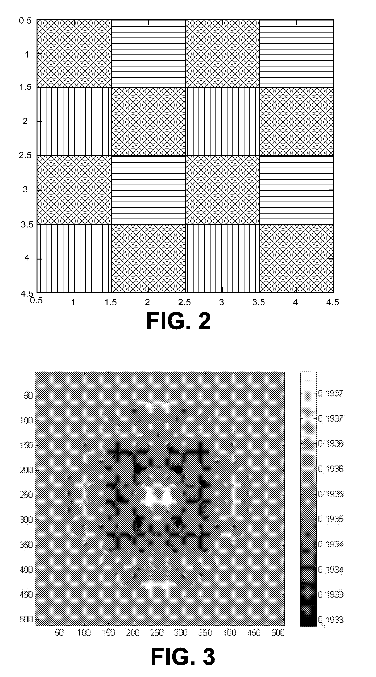
[0027]These numerical examples show how a slowly varying αi,j can be invisible during checkerboard calibration but create a line width deviation of significant size. The example here will be calibrated manually but the principle of it should still be clear. The SLM model is such that 20 (V) is approximately black and 10 (V) is used as white. The increment 0.1 (V) represents the smallest change that can be made when an 8 bit word length is used by the calibration program.

[0028]First we define a local Gaussian disturbance using the symbol ε, so that we can continue to use the symbol α in the general from of the equation C+αP without confusion.

ε=exp(−(i2+j2) / 102)   (2)

A slowly varying pattern across a drifting checkerboard calibration, which is impacted by the disturbance, can be expressed by

V=10(1−C)+(20+0.017ε)C+0.5εP   (3)

and is shown FIG. 3.

[0029]Strictly speaking, this is not a calibrated pattern, because the gray values vary across the field (they are not uniform). Effectively th...


PUM


Abstract

The present disclosure relates to phase-sensitive calibration of an SLM system. In particular, it relates to selecting among local calibrations when there is more than one calibration that satisfies a calibration intensity criteria. It utilizes information available before Fourier filtering, from non-zeroth order diffraction components to counter drift among alternative local calibrations.

Description

RELATED APPLICATIONS[0001]This application is related to U.S. patent application Ser. No. 10 / 238,220, filed on 10 Sep. 2002, entitled “IMPROVED METHOD AND APPARATUS USING AN SLM” by inventors Torbjorn Sandstrom and Jarek Luberek. It also is related to U.S. patent application Ser. No. 09 / 995,526, filed on 28 Nov. 2001, entitled “DEFECTIVE PIXEL COMPENSATION METHOD” by inventor Torbjorn Sandstrom. It also is related to U.S. patent application Ser. No. 10 / 410,874, filed on 10 Apr. 2003, entitled “METHODS AND SYSTEMS FOR PROCESS CONTROL OF CORNER FEATURE EMBELLISHMENT” by inventors Torbjorn Sandstrom, Hans Martinsson, Niklas Eriksson and Jonas Hellgren. It also is related to U.S. patent application Ser. No. 10 / 757,351, filed on 14 Jan. 2004, entitled “METHOD TO DETECT A DEFECTIVE ELEMENT” by inventor Peter Durr. The related applications are incorporated by reference.BACKGROUND OF THE INVENTION[0002]The present disclosure relates to phase-sensitive calibration of a spatial light modulato...

Claims


Application Information

Patent Timeline
IPC IPC(8): G01N21/84G02B27/46
CPCG02B27/46G03F7/70191G03F7/70516G03F7/70291G03F7/70283
Inventor LUBEREK, JAREK
Owner MICRONIC LASER SYST AB
Why Eureka
Try Eureka