
Backlight module with diffusion sheet having a subwavelength grating

a subwavelength grating and diffusion sheet technology, applied in the direction of diffusing elements, instruments, optics, etc., can solve the problems of low light utilization efficiency and low module b>1/b> and achieve high light utilization efficiency and high uniformity of outgoing light

Inactive Publication Date: 2005-09-08
HON HAI PRECISION IND CO LTD
View PDF12 Cites 14 Cited by
  • Summary
  • Abstract
  • Description
  • Claims
  • Application Information

AI Technical Summary

Benefits of technology

[0009] An object of the present invention is to provide a diffusion sheet which has a high light utilization efficiency and high uniformity of outgoing light.
[0012] When light beams propagate through the subwavelength grating, they are diffracted forward and backward to form front diffraction waves and back diffraction waves. Because the subwavelength grating is a zeroth-order grating, it only propagates the zeroth-order diffraction waves. Therefore, based on diffraction theory, the back diffraction waves can be eliminated by adjusting the period T and the shape of the subwavelength grating. If this is done, almost all the incident light beams are transmitted through the incident surface. The efficiency of light utilization is thereby enhanced.
[0013] Moreover, when the light beams propagate through the subwavelength grating, the light beams are diffracted and distributed uniformly. Accordingly, the diffusion sheet yields high uniformity of outgoing light emitted from the emitting surface.

Problems solved by technology

However, repetitious reflection makes the backlight module 1 yield a low uniformity of outgoing light.
Moreover, some of the light beams are absorbed by the reflector, so that light utilization efficiency is deceased.

Method used


Image

  • Backlight module with diffusion sheet having a subwavelength grating
  • Backlight module with diffusion sheet having a subwavelength grating
  • Backlight module with diffusion sheet having a subwavelength grating

Examples


first embodiment

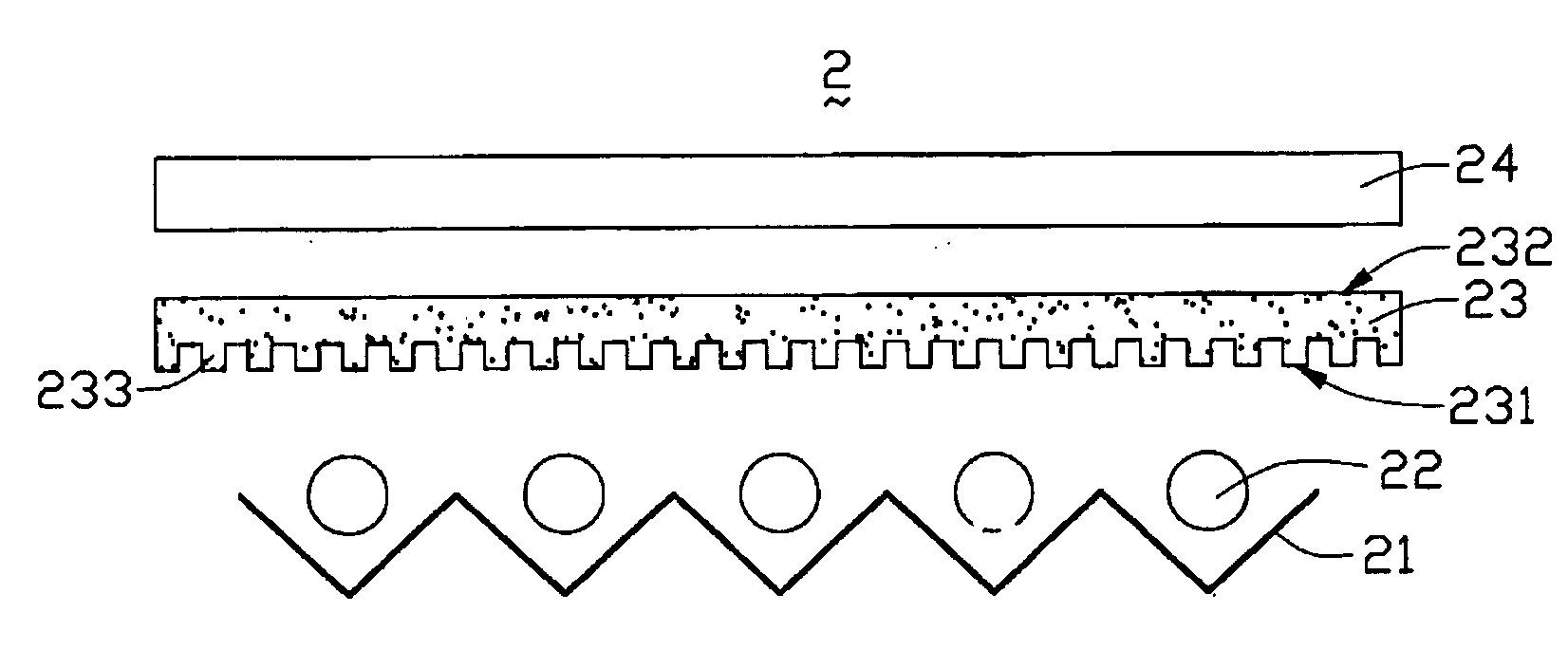
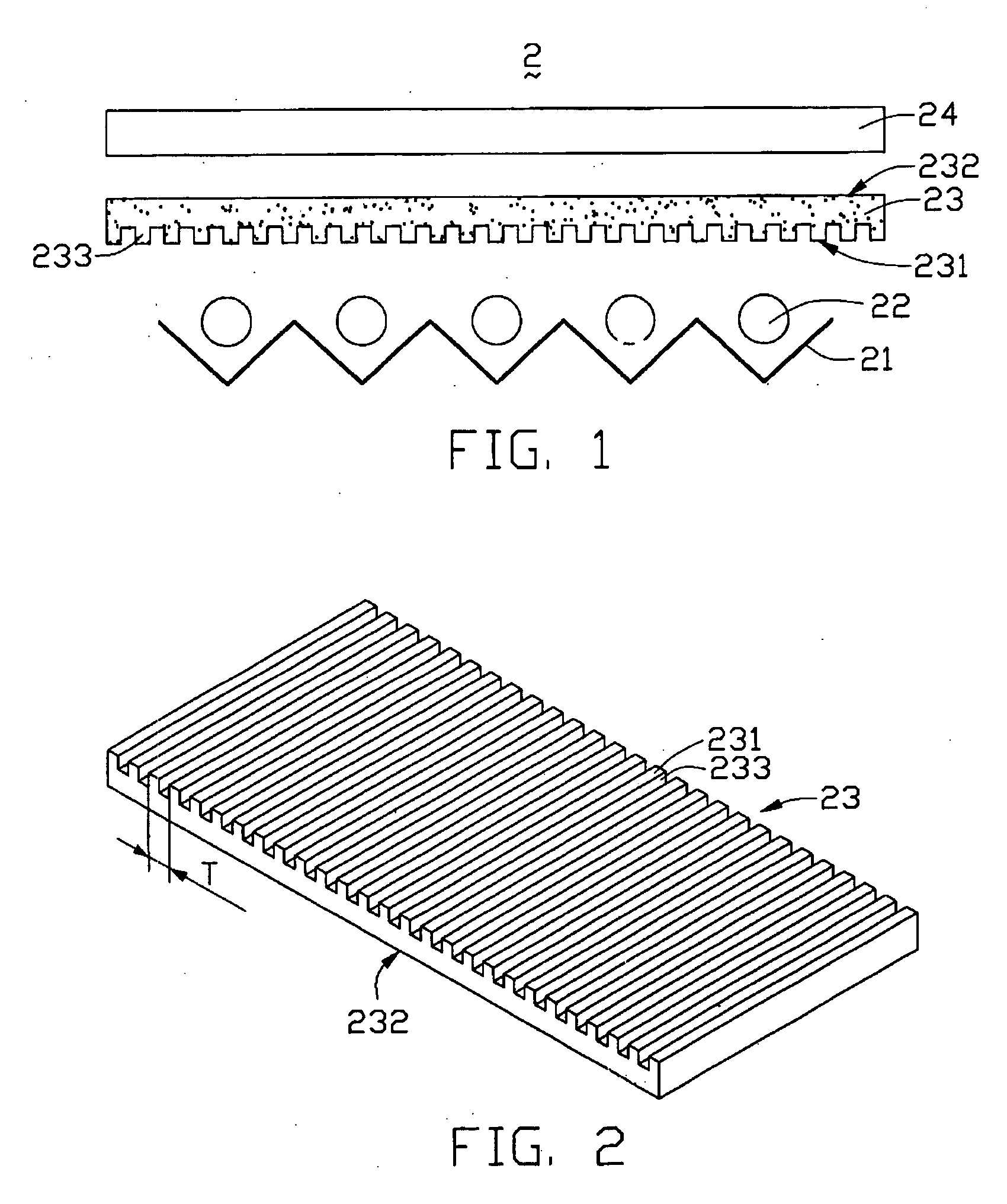
[0024] Also referring to FIG. 2, an isometric view of a first embodiment the diffusion sheet 23 is shown. The diffusion sheet 23 is made of a transparent organic resin material, such as polymethyl methacrylate (PMMA), polycarbonate (PC) or the like. The diffusion sheet 23 has a light incident surface 231 facing the light sources 22 and a light emitting surface 232. The diffusion sheet 23 includes a plurality of light scattering particles (not labeled) therein. The incident surface 231 has a subwavelength grating 233 formed thereat. The subwavelength grating 233 is integrally formed as part of the diffusion sheet 23. The subwavelength grating 233 defines a plurality of parallel channels, and each of the channels defines a rectangular cross-section.

[0025] In operation, the light sources 22 emit light beams. When the light beams propagate through the subwavelength grating 233, they are diffracted forward and backward, to form front diffraction waves and back diffraction waves. Because ...

second embodiment

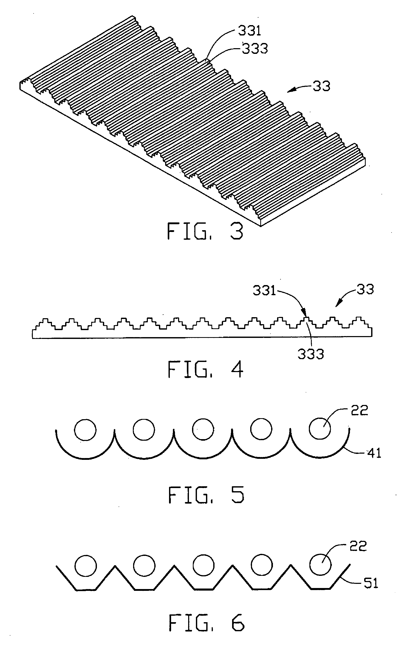
[0027] Referring to FIGS. 3 and 4, a second embodiment diffusion sheet 33 of the present invention is shown. The diffusion sheet 33 has a light incident surface 331. The diffusion sheet 33 includes a plurality of light scattering particles (not shown) therein. The incident surface 331 has a subwavelength grating 333 formed therein. The subwavelength grating 333 defines a plurality of parallel generally v-shaped or pyramid-shaped cuts.

[0028] Referring to FIG. 5, an alternative reflector 41 is shown. The reflector 41 comprises a plurality of contiguous semicylindrical portions, the semicylindrical portions at least partially receiving the light sources 22 respectively.

[0029] Referring to FIG. 6, a further alternative reflector 51 is shown. The reflector 51 comprises a plurality of contiguous polygonal-shaped portions, the polygonal-shaped portions at least partially receiving the light sources 22 respectively.


PUM


Abstract

A diffusion sheet (23) of the present invention includes a light incident surface (231) having a subwavelength grating (233) formed thereat, and a light emitting surface (232) opposite to the light incident surface. When light beams propagate through the subwavelength grating, they are diffracted forward and backward, to form front diffraction waves and back diffraction waves. Because the subwavelength grating is a zeroth-order grating, it only propagates the zeroth-order diffraction waves. Therefore, based on diffraction theory, the back diffraction waves can be eliminated by adjusting the period T and the shape of the subwavelength grating. If this is done, almost all the incident light beams are transmitted through the incident surface. Thereby, the efficiency of light utilization is enhanced. Moreover, the light beams are diffracted and distributed uniformly. Accordingly, the diffusion sheet yields high uniformity of outgoing light emitted from the emitting surface.

Description

BACKGROUND OF THE INVENTION [0001] 1. Field of the Invention [0002] The present invention relates to a diffusion sheet having a subwavelength grating for controlling light transmission, and to a direct type backlight module for liquid crystal display devices employing such a diffusion sheet. [0003] 2. Description of the Prior Art [0004] A typical LCD device comprises an LCD panel, and a backlight module mounted under the LCD panel for supplying light beams thereto. There are two types of backlight modules: the edge type and the direct type. The edge type backlight module mainly comprises a light guide plate, and a light source disposed adjacent to a thin side of the light guide plate. The light guide plate is used for guiding the light beams emitted by the light source to uniformly illuminate the LCD panel. [0005] In contrast, the direct type backlight module employs light sources placed in an air-filled cavity under the LCD panel, and a diffuser disposed between the LCD panel and t...

Claims


Application Information

Patent Timeline
IPC IPC(8): G02B13/20
CPCG02B5/0215G02F2201/30G02F1/133606G02B5/0242
Inventor YU, TAI-CHERNGLEU, CHARLESCHEN, GA-LANE
Owner HON HAI PRECISION IND CO LTD
Learn More