Seeded raman amplifier for applications in the 1100-1500 nm spectral region

Active Publication Date: 2013-06-25
THE UNITED STATES OF AMERICA AS REPRESETNED BY THE SEC OF THE AIR FORCE
View PDF11 Cites 16 Cited by
  • Summary
  • Abstract
  • Description
  • Claims
  • Application Information

AI Technical Summary

Benefits of technology

The present invention is a system that can operate with high power and has a controllable linewidth. It uses a rare-earth amplifier directly connected to a Raman resonator, resulting in high power output compared to traditional systems. By using a rare-earth amplifier instead of an oscillator that builds up power levels in the cavity, the system can achieve higher power levels and higher conversion efficiencies. Additionally, the system has measures in place to mitigate stimulated brillouin scattering, such as offsets of Bragg grating pairs and the use of high dispersion raman fiber. Compatible with various techniques to mitigate SBS, the system can be used in different types of fibers and operational modes.

Problems solved by technology

In general, there is a lack of efficient, high-power lasers in the 1100-1500 nm region with a controllable linewidth.
Lasers in the 1100-1500 nm spectral region are difficult to obtain, since many materials don't lase in this region and those that do lase in parts of the spectral region such as bismuth co-doped silica or Yb-doped silica, do so inefficiently.
Such amplifiers typically tend to have low Raman conversion efficiencies and low output powers (<5 W) due to the relatively low intensity of injected pump signal in the core.
Because both WDMs and optical circulators are power limited, the amount of pump signal (zeroth order Stokes) and desired output signal (Nth order Stokes) that can be fed into the system is limited.
Because of low levels of pump signal in the system, output power levels are limited, efficiencies tend to be low, and extremely long Raman fibers (100 m or more) are necessary.
Output power levels are also limited by Stimulated Brillouin Scattering for narrow linewidth signals due to the long Raman fiber.
This configuration will also be power limited relative to what would be achievable using a comparable rare earth doped amplifier because of thermal issues associated with power buildup in the cavity of the rare earth doped oscillator.
In addition, the embodiment in this patent application may experience damage upstream, since no measures are taken to mitigate light leaking out of the gratings and propagating backwards.
Also, high power levels within the rare earth doped oscillator and the Raman cavities may be a limiting issue.
This is important since the resolution of terrestrial telescopes is limited by wave front distortion caused by atmospheric turbulence.
The sodium guidestar laser application is very challenging in that output powers on the order of 50 W of 589.15908 nm on the sodium D2a line with a linewidth of 10 MHz is required.
The major drawback associated with this system is its size and complexity.
The bottleneck associated with this technique is a power limitation associated with the WDM that clamps the amount of 1121 nm that can be injected into the system.
This, coupled with problems from SBS resulting from a Raman fiber of length 150 meters, results in relatively low output powers of 1178 nm.
The result is a system of increased complexity.
Such lasers are inefficient and typically of low output power because of having to insert and remove light through power sensitive components.
Such lasers can be of rather high output power but are of broad linewidth because of the lack of a seed or other measures to control the linewidth.

Method used


Image

  • Seeded raman amplifier for applications in the 1100-1500 nm spectral region
  • Seeded raman amplifier for applications in the 1100-1500 nm spectral region
  • Seeded raman amplifier for applications in the 1100-1500 nm spectral region

Examples


Embodiment Construction

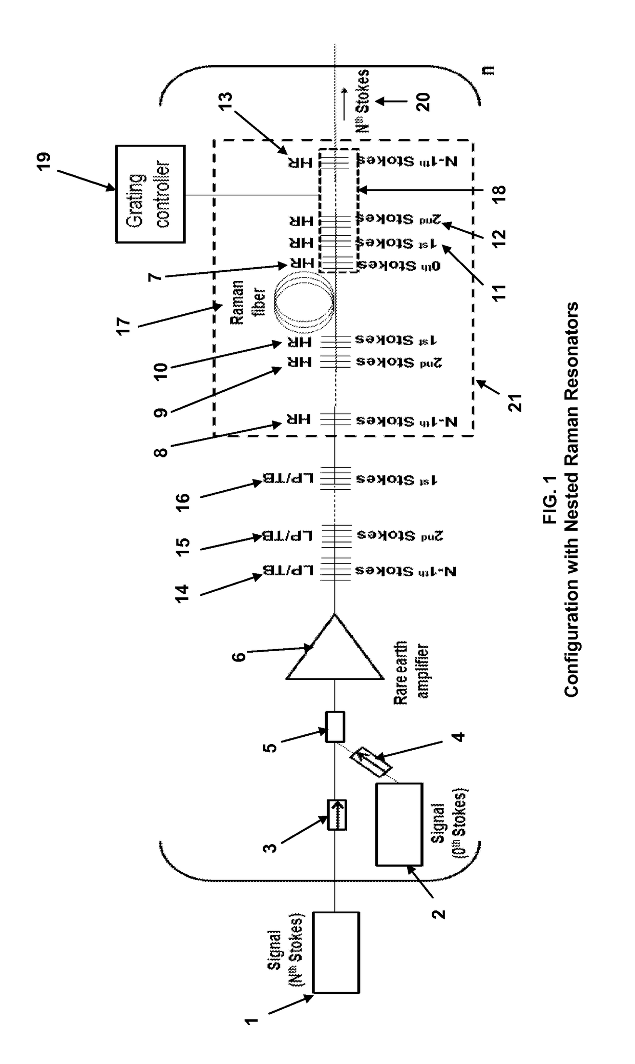
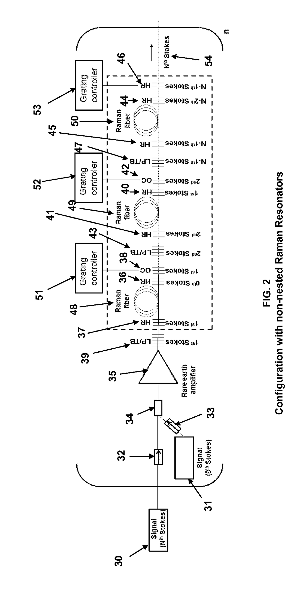
[0031]The two generic embodiments representing the extremes of Raman resonator configurations for the invention described in this patent are described. One embodiment consists of a rare earth doped fiber amplifier spliced to a Raman resonator configuration that is fully nested. The other embodiment consists of a rare earth doped fiber amplifier spliced to a completely linear, unnested, Raman resonator configuration. Anyone skilled in the art will realize that other configurations lying between these two extremes are possible.

Nested Raman Resonator Embodiment

[0032]A block diagram of the fully nested Raman resonator embodiment is shown in FIG. 1. The first device in the diagram is a seed source 1 tuned to the desired output wavelength, the Nth order Stokes line. It may be created in a number of ways to include frequency doubling of a source at a longer wavelength. This device needs to have the linewidth desired of the output. Another device in the diagram is a seed source 2 tuned to t...


PUM


Abstract

A method of generating high-power laser output in the 1100 to 1500 um spectral region having a controllable linewidth. A Raman amplifier comprised of one or more nested pairs of fiber Bragg grating cavities tuned to the 1st, 2nd, . . . N−1st order Stokes wavelengths is seeded with both the desired Nth order Stokes output wavelength and the corresponding zeroth-order Stokes pump wavelength. As the pump wavelength propagates through the apparatus, it is sequentially converted to the 1st, 2nd, . . . N−1st order Stokes wavelengths in the nested fiber Bragg grating cavities. The desired Nth order Stokes output wavelength is then amplified by the N−1st Stokes order as it propagates through the nested fiber Bragg grating cavities. The linewidths of various Stokes orders can be controlled through adjusting resonant bandwidths of the fiber Bragg grating cavities by offsetting, through heating, the reflectivity bandwidths of each pair of cavity gratings.

Description

STATEMENT OF GOVERNMENT INTEREST[0001]The conditions under which this invention was made are such as to entitle the Government of the United States under paragraph 1(a) of Executive Order 10096, as represented by the Secretary of the Air Force, to the entire right, title and interest therein, including foreign rights.BACKGROUND OF THE INVENTION[0002]The invention relates generally to high-power Raman amplifier systems having linewidths from narrow to broad, functioning in the near-infrared spectral region for numerous applications. Such applications include a narrow linewidth 1178 nm sodium guidestar laser for improved space situational awareness, a 1240 nm source for remote sensing of water, and 1300-1500 nm lasers for telecommunications.[0003]In general, there is a lack of efficient, high-power lasers in the 1100-1500 nm region with a controllable linewidth. Lasers in the 1100-1500 nm spectral region are difficult to obtain, since many materials don't lase in this region and those...

Claims


Application Information

Patent Timeline
IPC IPC(8): H01S3/30
CPCH01S3/302H01S3/0675H01S3/06754H01S3/0826H01S3/1053H01S3/1055H01S3/10092H01S3/06725H01S3/108H01S3/1086H01S3/1655H01S3/2316H01S3/30H01S5/5027
Inventor HENRY, LEANNE J.SHAY, THOMAS M.MOORE, GERALD T.GROSEK, JACOB R.
Owner THE UNITED STATES OF AMERICA AS REPRESETNED BY THE SEC OF THE AIR FORCE
Why Eureka
Try Eureka