Antenna device for a portable terminal

Active Publication Date: 2011-09-01
SAMSUNG ELECTRONICS CO LTD +1
View PDF9 Cites 15 Cited by
  • Summary
  • Abstract
  • Description
  • Claims
  • Application Information

AI Technical Summary

Benefits of technology

[0018]According to the present invention, since an antenna device includes first and second antenna patterns and the second antenna pattern is formed of a zeroth mode resonator, the second antenna pattern is easily operated as an antenna for a low frequency band (for example, a ground-wave DMB service band of 200 MHz). Since the resonance frequency of the zeroth mode resonator can be adjusted by adjusting capacitance components (capacitances) and inductance components (inductances) irrespective of the physical size thereof, an antenna device capable of operating at a low frequency band can be easily formed.
[0019]Accordingly, th

Problems solved by technology

Due to many efforts for improving the performances of antenna devices according to changes in the mobile communication service environment, there have been many difficulties in realizing antenna devices capable of simultaneously receiving mobile communication services provided at different frequency bands while it becomes possible to transmit data of high capacity through which videos can be watched and an internet service can be used in real time at a high speed.
That is, when an antenna device is manufactured by combining antenna elements operated at different frequency bands, the operation characteristics of the antenna elements are unavoidably distorted due to the interferences be

Method used


Image

  • Antenna device for a portable terminal
  • Antenna device for a portable terminal
  • Antenna device for a portable terminal

Examples


Embodiment Construction

[0027]Hereinafter, exemplary embodiments of the present invention will be described with reference to the accompanying drawings. In the following description of the present invention, a detailed description of known functions and configurations incorporated herein will be omitted when it may make the subject matter of the present invention rather unclear.

[0028]It is noted that while expressions such as ‘relatively high’ and ‘relatively low’ are used in the following description of the present invention, they are used to compare the operation characteristics of a first antenna pattern and a second antenna pattern that will be described hereinbelow.

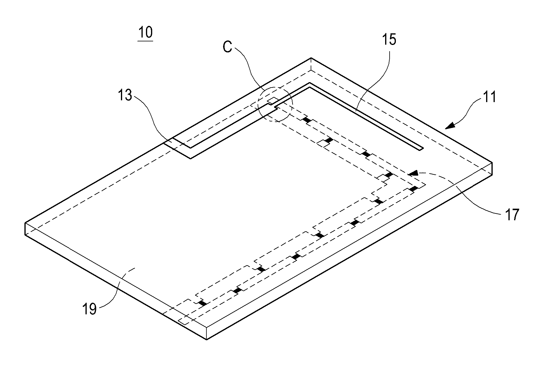
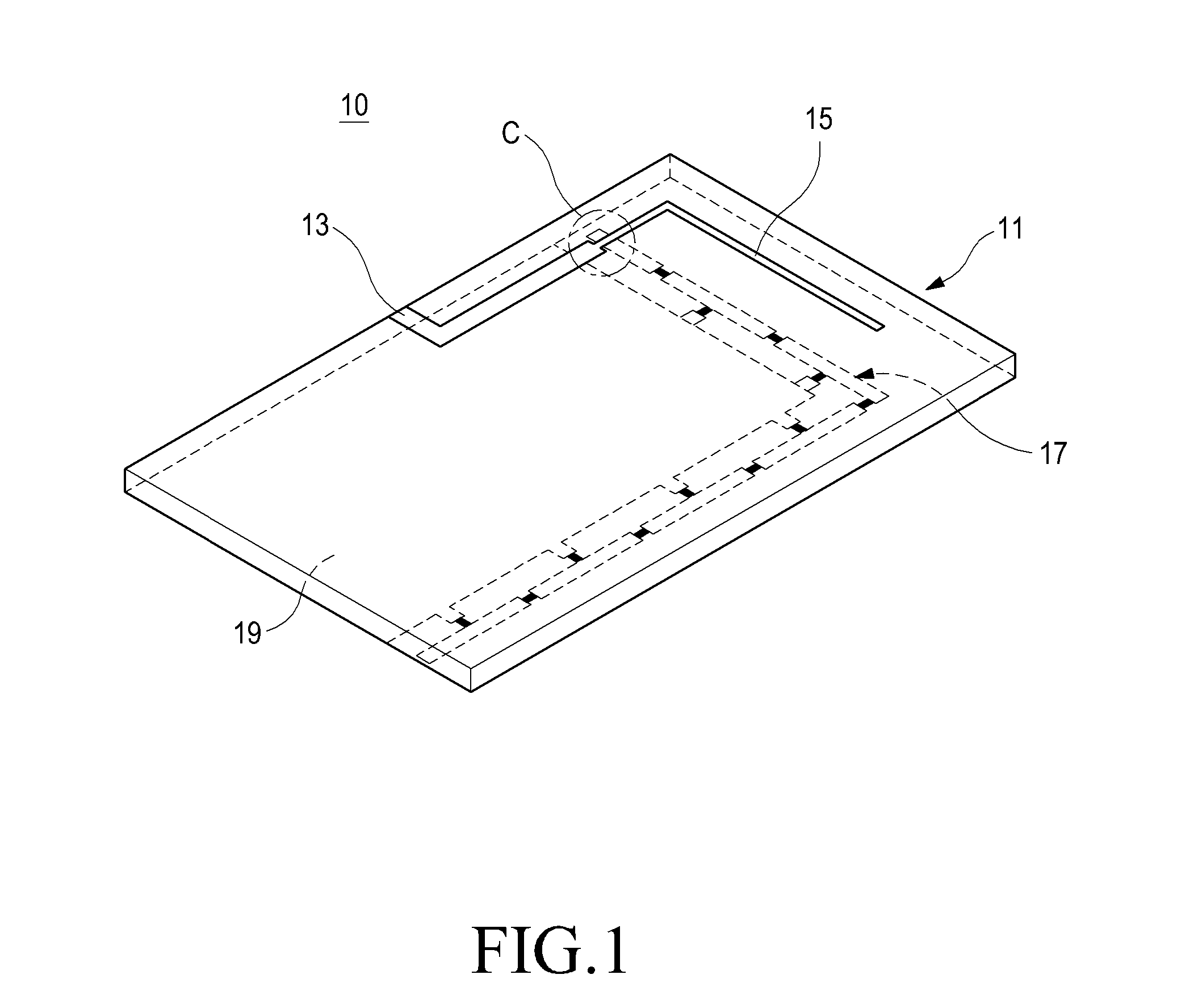
[0029]FIG. 1 is a perspective view illustrating an antenna device 10 for a portable terminal according to an embodiment of the present invention. As illustrated in FIG. 1, the antenna device 10 includes a ground pattern 19 provided on one surface of a circuit board 11, and a second pattern 17 formed along a periphery of the ground pattern 1...


PUM


Abstract

An antenna device for a portable terminal includes: a ground pattern provided on one surface of a circuit board; a first antenna pattern configured to resonate at a first frequency band and provided on an opposite surface of the circuit board; and a second antenna pattern configured to resonate at a second frequency band different from the first frequency band and arranged along a periphery of the ground pattern. The second antenna pattern is a zeroth order mode resonator including a plurality of capacitors and a plurality of inductors. The antenna device easily secures the operation characteristics of different operation frequency bands and contributes to miniaturization of the portable terminal. Thus, a user can conveniently carry and use the portable terminal.

Description

TECHNICAL FIELD[0001]The present invention relates to a portable terminal, and more particularly to an antenna device that allows a user to use various mobile communication services provided at different frequency bands through a single portable terminal.BACKGROUND ART[0002]In general, an antenna device for a portable terminal refers to a device that allows a user to use mobile communication services through a portable terminal by performing wireless communications with a mobile communication base station.[0003]Mobile communication services provided through a portable terminal at the initial stage were, for example, voice communications and transmission of short messages which were commercialized by simple communications through which data of low capacity were transmitted and received at a low speed. However, in recent years, various types of services such as transmission of videos, real-time searches through the internet, digital multimedia broadcasting (hereinafter, referred to as...

Claims


Application Information

Patent Timeline
IPC IPC(8): H01Q1/38H01Q9/06
CPCH01Q1/243H01Q5/378H01Q9/42H01Q1/48H01Q1/24H01Q1/38
Inventor BYUN, JOON-HOHWANG, SOON-HOKIM, MUN-ILKIM, DO-WONPARK, HYUN-SEOK
Owner SAMSUNG ELECTRONICS CO LTD
Why Eureka
Try Eureka