
Structural hybrid attachment system and method

a hybrid attachment system and structure technology, applied in the direction of roofs, other domestic objects, transportation and packaging, etc., can solve the problems of consuming valuable labor time, affecting the efficiency of the vehicle, so as to achieve the effect of effective load distribution within the vehicl

Inactive Publication Date: 2009-01-08
INTEVA PRODUCTS LLC
View PDF18 Cites 31 Cited by
  • Summary
  • Abstract
  • Description
  • Claims
  • Application Information

AI Technical Summary

Benefits of technology

The present invention provides an integrated structural system for vehicles that attaches components, reinforces load bearing areas, and effectively distributes loads. The system includes a molded duct system and a metal structure integrated with the duct system. The metal structure can be sonic welded, heat staked, insert molded, or glued onto the duct system. The integrated structural load path assembly acts as a load bearing area to distribute loads on the supporting surface. The system can be used to attach various vehicle components, such as a steering column, air bag, instrument panel, audio device, video device, HVAC assembly, and storage compartment. The system reduces extra parts needed for assembly, simplifies the design, and allows for easy installation. Overall, the invention provides a lightweight and strong structural system for vehicles that efficiently distributes loads and forces.

Problems solved by technology

A metal-to-plastic interface between the nut / bolt arrangement and the air duct tends to degrade the plastic of the air duct.
The attachment of the steering column structural support and the cross-car structural beam using the nut / bolt arrangement must be performed manually and requires the handling of several parts and tools, thus valuable labor time is consumed and extra expense incurred.

Method used


Image

  • Structural hybrid attachment system and method
  • Structural hybrid attachment system and method
  • Structural hybrid attachment system and method

Examples


Embodiment Construction

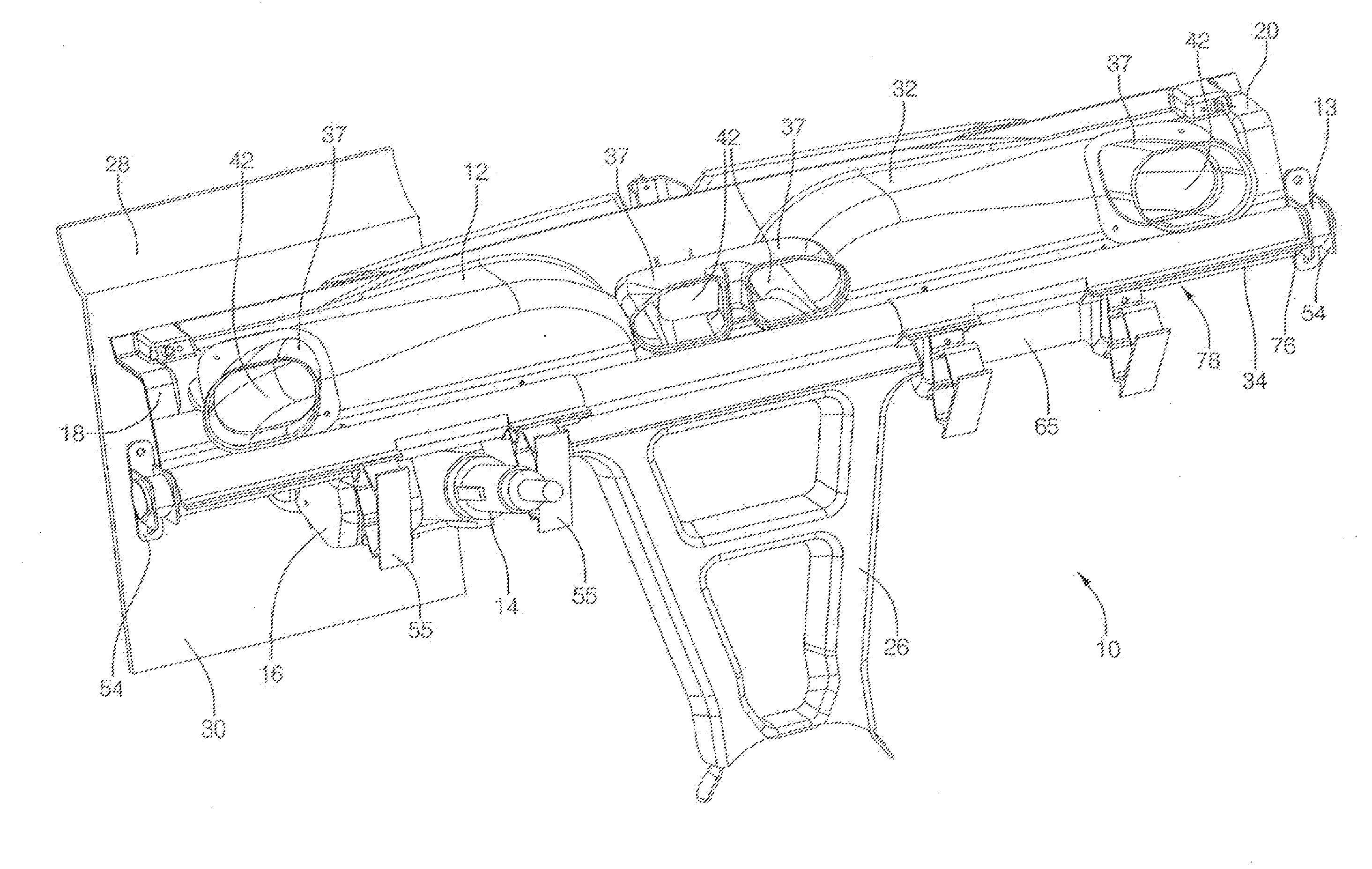
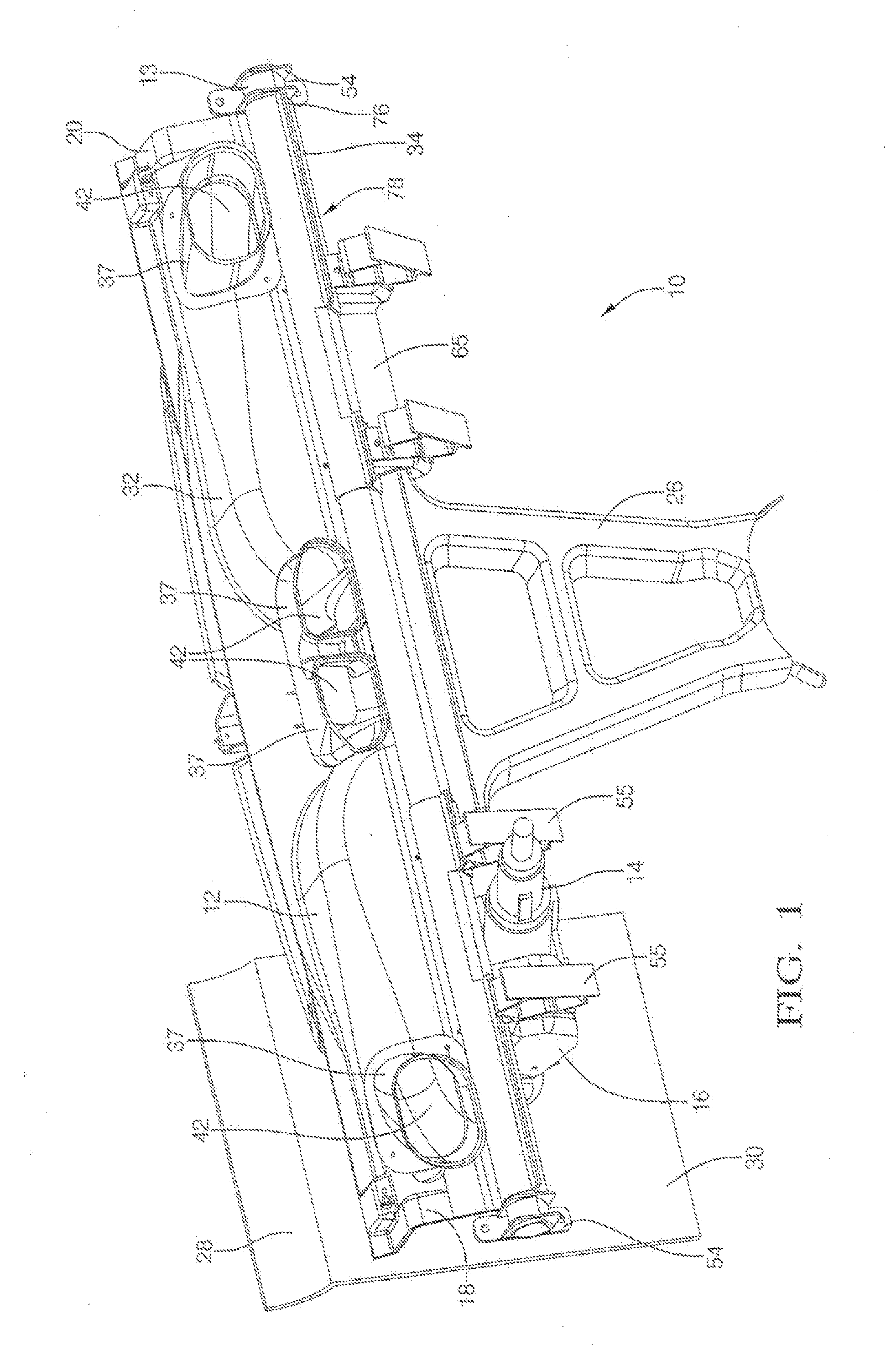
[0042]FIG. 1 illustrates a front perspective view of a structural hybrid support system 10 in one embodiment of the present invention.

[0043]Structural support system 10 is located within a vehicle. Structural hybrid support system 10 includes a first structural member 12, a metal structure 13 configured as a metal tube 13, and a vehicle component 14. First structural member 12, tube 13 and vehicle component 14 are disposed adjacent to one another.

[0044]Structural support system 10 also includes an attachment assembly 16 positioned relative to first structural member 12, tube 13 and vehicle component 14. Attachment assembly 16 attaches vehicle component 14 to first structural member 12 and tube 13 and facilitates the distribution of loads of vehicle component 14 across first structural member 12 and tube 13.

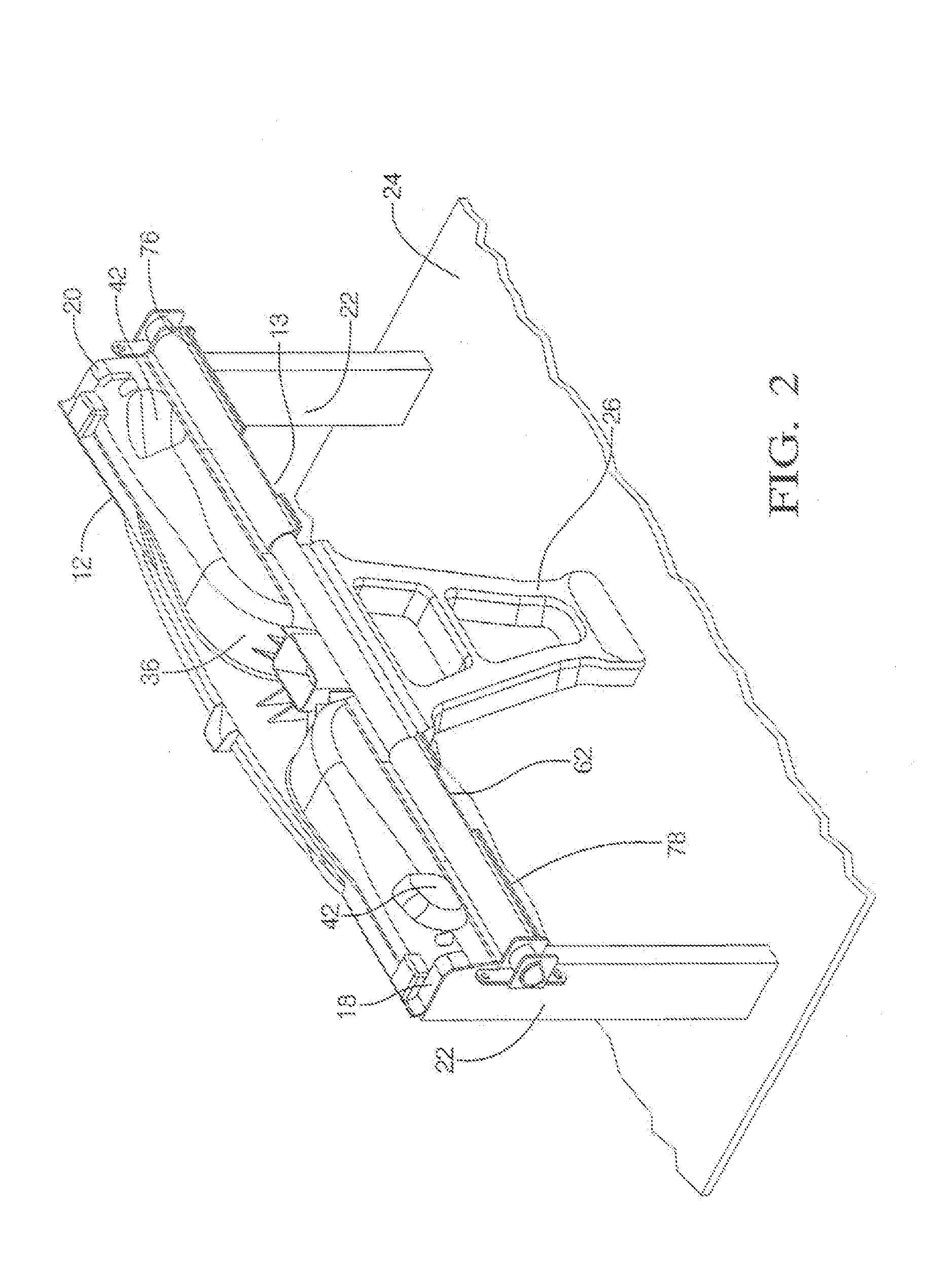
[0045]Referring now to FIGS. 1-3, first structural member 12 is a structural air duct assembly. Structural air duct assembly 12 includes opposing ends 18 and 20. Opposing ends 18 ...


PUM

PropertyMeasurementUnit
lengthaaaaaaaaaa
lengthaaaaaaaaaa
mechanicalaaaaaaaaaa

Abstract

An integrated structural system for a vehicle is provided. The integrated structural system includes a molded duct system configured to guide airflow having a first section and a second section and configured to operably attach a vehicle component thereto. The integrated structural system also includes a metal structure integrated with the molded duct system by means for integrating the metal structure with the molded duct system forming an integrated structural load path assembly. The integrated structural load path assembly is configured as a load bearing area to distribute a load of the vehicle component operably attached thereto. The means for integrating the metal structure with said molded duct system include, but not limited to, at least one of, sonic welding, heat staking, insert molding, and gluing.

Description

CROSS REFERENCE TO RELATED APPLICATION[0001]The present application is a divisional of U.S. patent application Ser. No. 10 / 846,003 filed May 14, 2004 now U.S. Pat. No. 7,128,360, which is a continuation-in-part of U.S. patent application, Ser. No. 10 / 316,683 filed Dec. 10, 2002, the contents each of which are incorporated herein by reference thereto.TECHNICAL FIELD[0002]The present invention relates generally to vehicle structural systems, and more particularly to a structural attachment system having features for attaching components to one another within a vehicle, for providing reinforcement in load bearing areas of the components, and for allowing effective distribution of loads within the vehicle.BACKGROUND OF THE INVENTION[0003]Typically, a steering assembly of a vehicle includes a steering column extending between a steering mechanism, for example, a steering wheel, and a torque distribution mechanism. The steering column is designed to translate rotation of the steering whee...

Claims


Application Information

Patent Timeline
Patent Type & Authority Applications(United States)
IPC IPC(8): B62D25/14B62D29/00
CPCB29L2031/3002B62D25/142B62D25/145Y10T29/49622B62D29/005B62D29/004Y10T29/49B62D29/001
Inventor SCHEIB, CHARLESMERRIFIELD, RICHARD ALLENWIDIN, RONALD F.
Owner INTEVA PRODUCTS LLC
Learn More