

Device for Plasma Treatment at Atmospheric Pressure
- Summary
- Abstract
- Description
- Claims
- Application Information
AI Technical Summary
Benefits of technology
Problems solved by technology
Method used
Image

Examples
Embodiment Construction
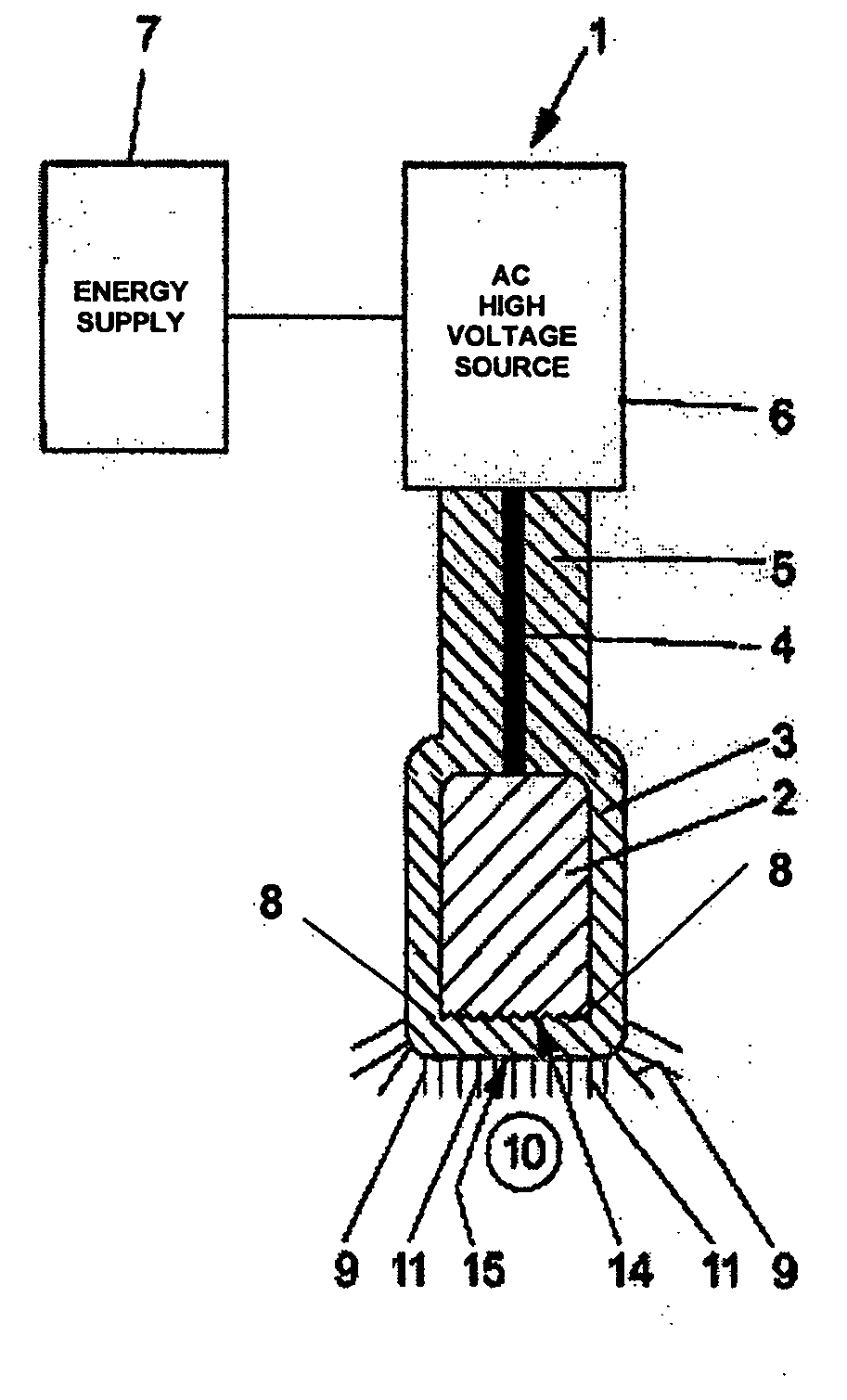
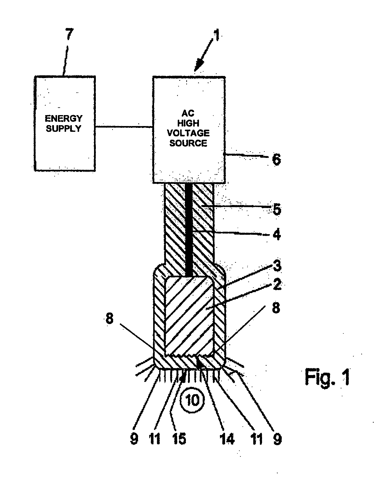
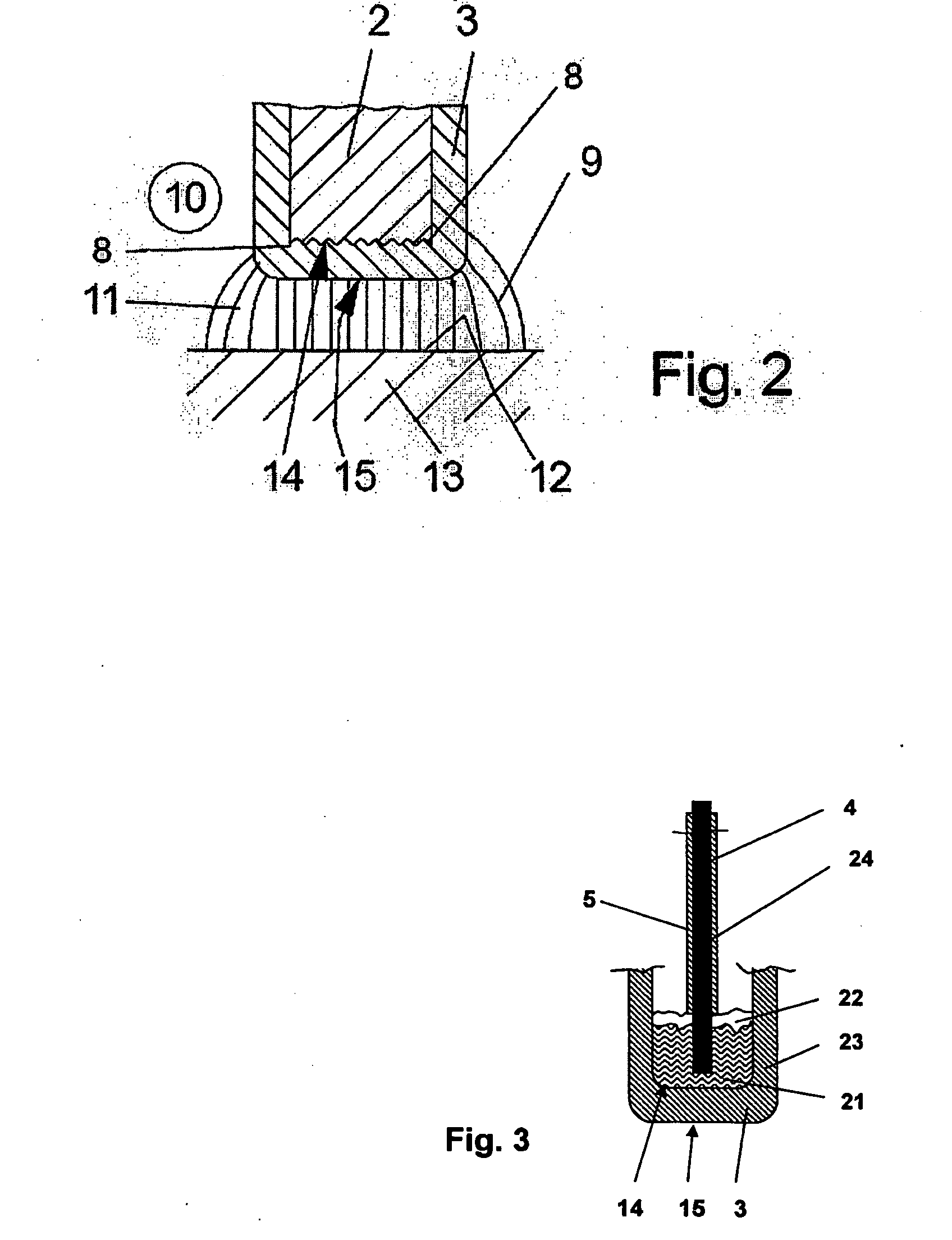
[0035]Referring now in greater detail to the drawings, FIG. 1 shows a device 1 for plasma treatment at atmospheric pressure of surfaces which are not depicted here. To this end, device 1 has an electrode 2 which is provided with a dielectric barrier 3 made of a suitable closed dielectric material, like for example a dense ceramic. A high voltage lead 4 having an electric isolation 5 connecting to dielectric barrier 3 leads to electrode 2. An AC high voltage is supplied to electrode 2 by an AC high voltage source 6 via high voltage lead 4. AC high voltage source 6 is based on semiconductor parts, and it is supplied with electric energy by an energy supply 7 which may be one or several batteries or accumulators or a mains adaptor. AC high voltage which will be more detailed explained with regard to FIG. 7 displays such a steep increase in voltage that a gas discharge 9 in the gas 10 at atmospheric pressure present in the surroundings of the electrode 2 is ignited and sustained over th...
PUM
 Abstract
Description
Claims
Application Information