Generating system with a regulated permanent magnet machine
- Summary
- Abstract
- Description
- Claims
- Application Information
AI Technical Summary
Benefits of technology
Problems solved by technology
Method used
Image

Examples
Embodiment Construction
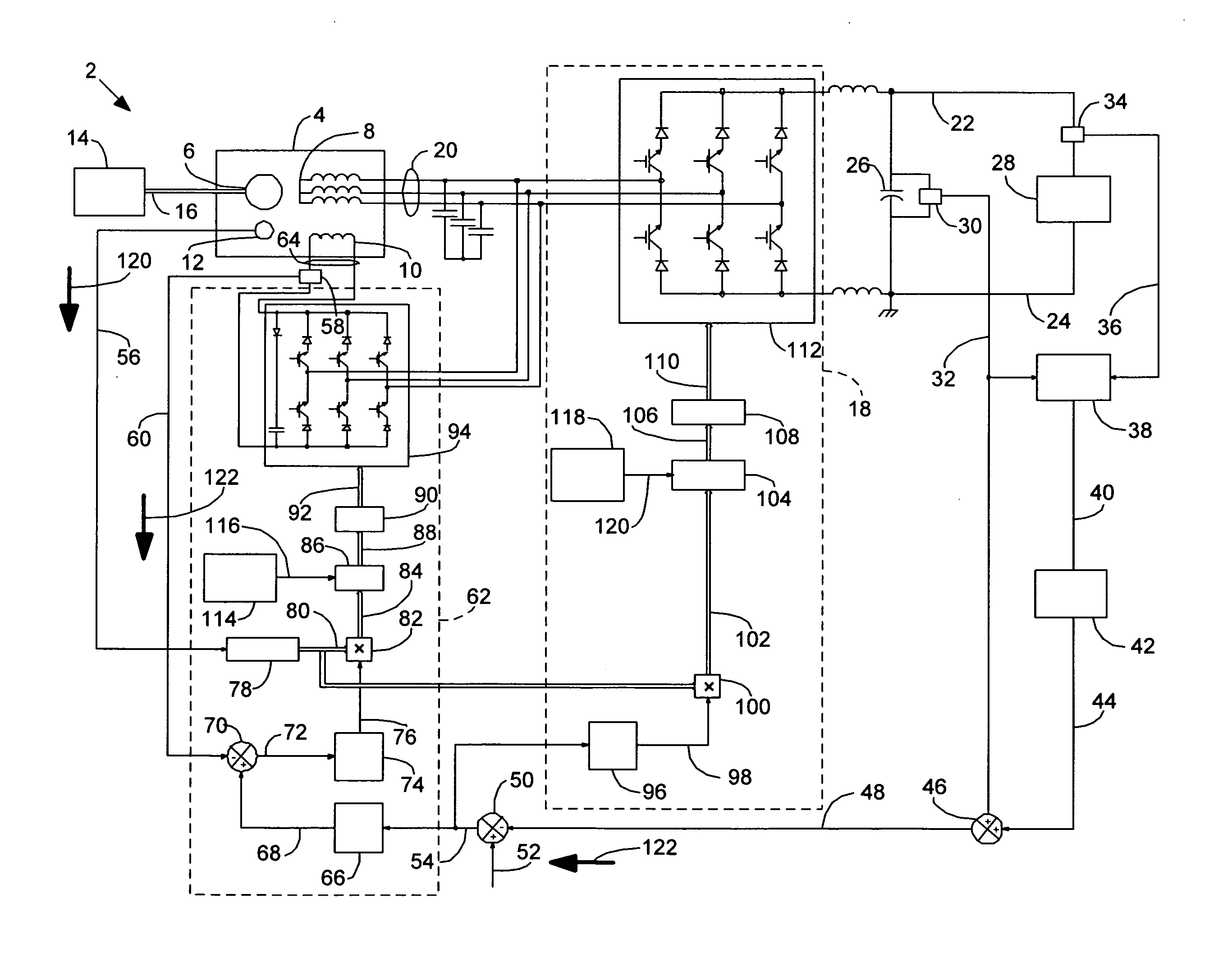
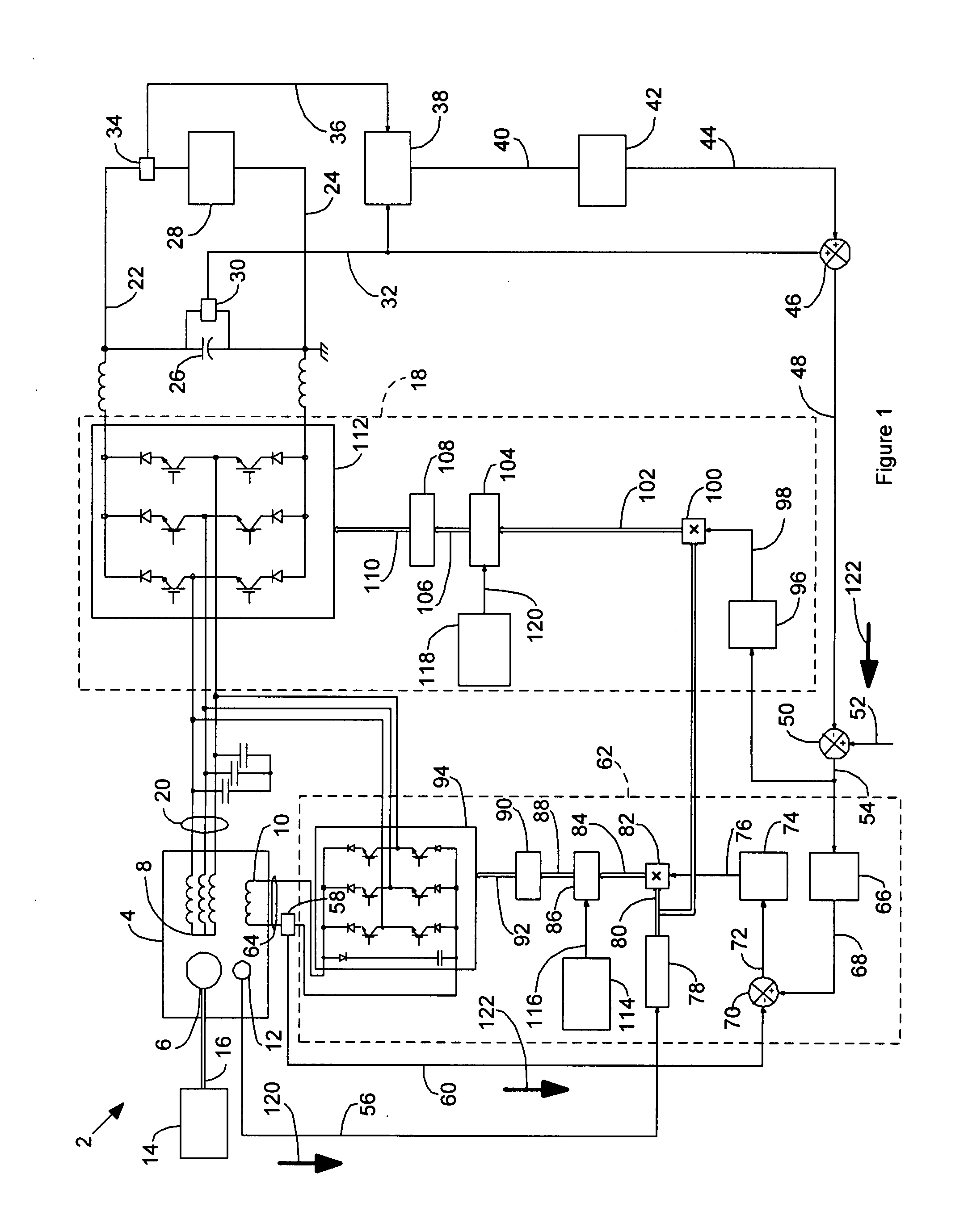
[0008]FIG. 1 is a high-level schematic diagram of an electrical power generation system 2 according to a possible embodiment of the invention. The electrical power generation system 2 comprises a PMM 4 that comprises a permanent magnet (PM) rotor 6, a stator 8, a magnetic control field generating control coil 10 and a position sensor 12. The rotor 6 comprises a permanent magnet type rotor. The stator 8 comprises a multiphase alternating current (AC) stator winding that is typically three phase AC. The control coil 10 comprises a winding in proximity to the stator winding 8 that is capable of generating a magnetic field with flux that passes through the stator winding 8 upon application of electrical current through the control coil 10. The position sensor 12 may be of any convenient type that is suitable for establishing the rotary position of the rotor 6.
[0009]PMM 4 may have any suitable construction. An example of a suitable construction is found in co-pending application Ser. Nos...
PUM
 Abstract
Description
Claims
Application Information
 - R&D
- Intellectual Property
- Life Sciences
- Materials
- Tech Scout
- Unparalleled Data Quality
- Higher Quality Content
- 60% Fewer Hallucinations
Browse by: Latest US Patents, China's latest patents, Technical Efficacy Thesaurus, Application Domain, Technology Topic, Popular Technical Reports.
© 2025 PatSnap. All rights reserved.Legal|Privacy policy|Modern Slavery Act Transparency Statement|Sitemap|About US| Contact US: help@patsnap.com