Three-Dimensional Representation Apparatus

a three-dimensional representation and apparatus technology, applied in the field of three-dimensional representation apparatuses, can solve the problems of jumbo size, difficulty in efficiently achieving an increase in the luminance of three-dimensional images without increasing the light quantity, etc., and achieve the effect of reducing cost, minimizing apparatus, and improving luminance and efficiency

Inactive Publication Date: 2009-01-08
ALPINE ELECTRONICS INC
View PDF10 Cites 40 Cited by
  • Summary
  • Abstract
  • Description
  • Claims
  • Application Information

AI Technical Summary

Benefits of technology

[0023]The three-dimensional representation apparatus may include two of the two-dimensional picture forming devices. With such configurations, by providing the two of the two-dimensional picture forming devices, the three-dimensional images composed of two of the two-dimensional pictures can be displayed, thereby further miniaturizing the apparatus and reducing cost.
[0024]Furthermore, the three-dimensional representation apparatus may be mounted on a vehicle. With such configurations, when the apparatus is incorporated in a head-up display on vehicle, the luminance and efficiency can be improved and the apparatus can be miniaturized.
[0025]Furthermore, the display optical element may be a concave mirror formed on a windshield o...

Problems solved by technology

However, in an apparatus using a parallax barrier, problems arise because of eye fatigue caused by viewing three-dimensional images for a long period of time.
Thus, in the three-dimensional representation apparatus 5 shown in FIG. 4, because luminance is reduced by an additional one-tenth due to the use of a second ...

Method used


Image

  • Three-Dimensional Representation Apparatus
  • Three-Dimensional Representation Apparatus
  • Three-Dimensional Representation Apparatus

Examples


first embodiment

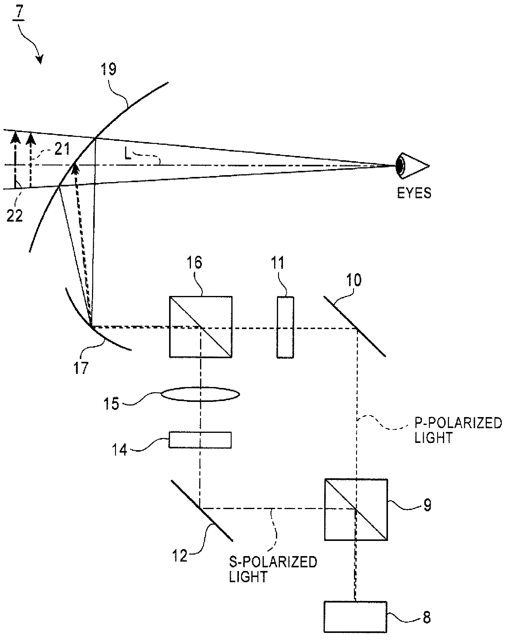
[0032]Implementations of a first embodiment of a three-dimensional representation apparatus are described below with reference to FIG. 1. As shown in FIG. 1, a three-dimensional representation apparatus 7 may include a light source 8 constituting part of a two-dimensional image forming apparatus. The light source 8 emits light including P-polarized linear light and S-polarized linear light, and may include a fluorescent lamp or a metal hydride lamp.

[0033]A first polarization beam splitter (PBS) (hereinafter referred to as a first polarization beam splitter 9) is arranged at a position on the light-emitting side of the light source 8 for serving as a spectroscopic optical element. The light emitted from the light source 8 enters the first beam splitter 9.

[0034]The first polarization beam splitter 9 allows the P-polarized light among the incident light from the light source 8 to pass through the first polarization beam splitter 9 in the same direction as the incidence direction from t...

second embodiment

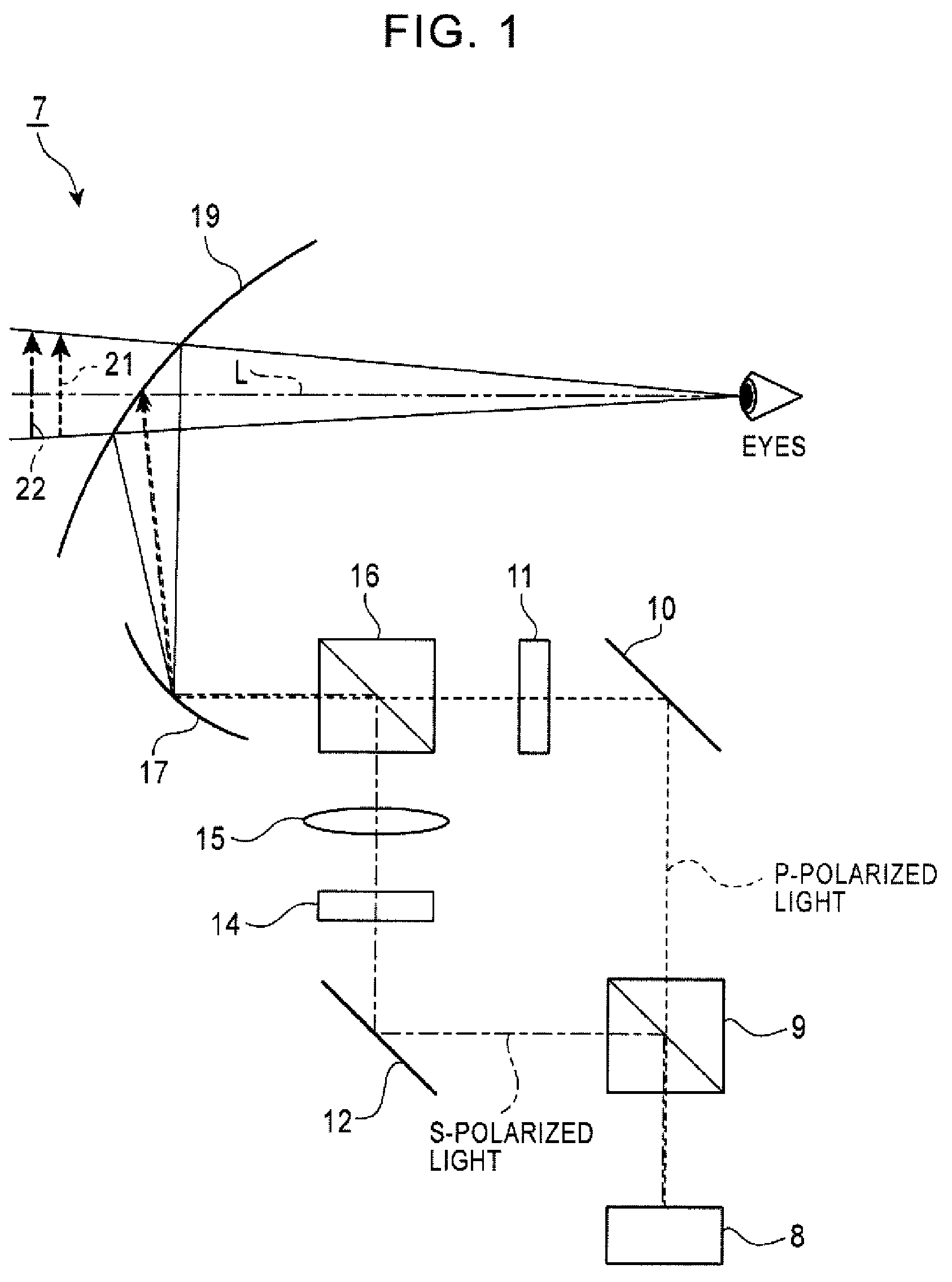
[0061]Implementations of a second embodiment of a three-dimensional representation apparatus are described with reference to FIG. 2, with an emphasis on differences with implementations of the first embodiment described above. Like reference characters designate like principal components common to the first embodiment, and the description will be made with reference to these.

[0062]As shown in FIG. 2, in some implementations of a three-dimensional representation apparatus 24, the configurations on the light path from the light source 8 to the second polarization beam splitter 16 are the same as some implementations of the three-dimensional representation apparatus 7 described above with respect to the first embodiment. However, as shown in FIG. 2, at a position on the first two-dimensional images transmission side as well as on the second two-dimensional images reflection side of the second polarization beam splitter 16, a collective lens 25 (a biconvex lens in FIG. 2) may be arrange...

third embodiment

[0067]Implementations of a third embodiment of a three-dimensional representation apparatus are described below with reference to FIG. 3. Like reference characters designate like principal components common to the first embodiment, and the description will be made with reference to these.

[0068]As shown in FIG. 3, a three-dimensional representation apparatus 27 may include a first light source (hereinafter referred to as a first light source 28) for emitting light. The first liquid crystal display panel 11 is positioned on the light emitting side of the first light source 28. The light emitted from the first light source 28 enters the first liquid crystal display panel 11. However, in some implementations, since the light incident in the first liquid crystal display panel 11 is not divided based on the polarized component unlike implementations of the first embodiment, the light includes light other than the P-polarized light (the S-polarized light, for example).

[0069]The first liqui...


PUM


Abstract

Three-dimensional representation apparatus are disclosed. In one implementation, the three-dimensional representation apparatus includes a first two-dimensional picture forming device configured to form a first two-dimensional picture and a second two-dimensional picture forming device configured to form a second two-dimensional picture. The luminance of the first and second two-dimensional pictures may be individually adjusted. The first and second two-dimensional picture forming devices are positioned to be out of light paths for projecting the two-dimensional pictures formed by the other two-dimensional picture forming device. The three-dimensional representation apparatus may also include a focal distance adjustment optical element configured to adjust focal distances for each of the first and second two-dimensional pictures differently. A picture combining optical element of the three-dimensional representation apparatus is configured to combine the first and second two-dimensional pictures comprising different focal distances along the same optical axis. A display optical element of the three-dimensional representation apparatus is configured to display three-dimensional images by allowing the two-dimensional pictures combined by the picture combining optical element to be projected as virtual images at focusing positions displaced from each other along a sight line of a user.

Description

RELATED APPLICATIONS[0001]The present application claims priority to Japanese Patent Application Serial Number 2007-178423, filed Jul. 6, 2007, the entirety of which is hereby incorporated by reference.FIELD OF THE INVENTION[0002]The present invention relates to three-dimensional representation apparatuses, and in particular relates to a three-dimensional representation apparatus suitable for representing three-dimensional images.BACKGROUND OF THE INVENTION[0003]Image displays may include a three-dimensional representation apparatus for three-dimensionally representing target images (hereinafter referred as to three-dimensional images). In such a three-dimensional representation apparatus, a number of apparatuses using a so-called anaglyph have been conventionally put to practical use, in which a user wearing dedicated eyeglasses can view three-dimensional images.[0004]Three-dimensional representation apparatuses for viewing three-dimensional images without wearing dedicated eyeglas...

Claims


Application Information

Patent Timeline
IPC IPC(8): H04N13/04
CPCG02B27/2278G02B27/26H04N13/0497H04N13/0402H04N13/0443G02B27/283H04N13/302H04N13/346H04N13/398G02B30/52G02B30/25
Inventor KAWAI, KIYOYUKI
Owner ALPINE ELECTRONICS INC
Why Eureka
Try Eureka