Projector

a projector and projector technology, applied in the field of projectors, can solve the problems of affecting the image quality of the projected image, so as to prevent the generation of color shading and prevent the degradation of the projected image quality

Inactive Publication Date: 2009-01-08
SEIKO EPSON CORP
View PDF0 Cites 9 Cited by
  • Summary
  • Abstract
  • Description
  • Claims
  • Application Information

AI Technical Summary

Benefits of technology

[0009]An advantage of some aspects of the invention is to provide a projector that can prevent the generation of color shading in the light projected onto a projection surface and hence prevent the degradation in image quality of the projected image.

Problems solved by technology

In such overlay projection, however, it is not easy to accurately superimpose the image light from the two projectors on the screen.
Inaccurate superimposition of the image light from the two projectors degrades the image quality of the projected image.
Therefore, among the image light projected onto the screen, the red light presents unevenness in the amount of light in the right-left direction (horizontal direction).
Therefore, among the image light projected onto the screen, the green light and the blue light also present unevenness in the amount of light in the right-left direction (horizontal direction).
As a result, the image light projected onto the screen presents unevenness in the amount of light in the right-left direction (horizontal direction).
When the polarized light from the illuminator that is not precisely collimated is incident on the liquid crystal panel, the image light projected on the screen tends to present even greater unevenness in the amount of light in the right-left direction (horizontal direction).

Method used


Image

  • Projector
  • Projector
  • Projector

Examples


first embodiment

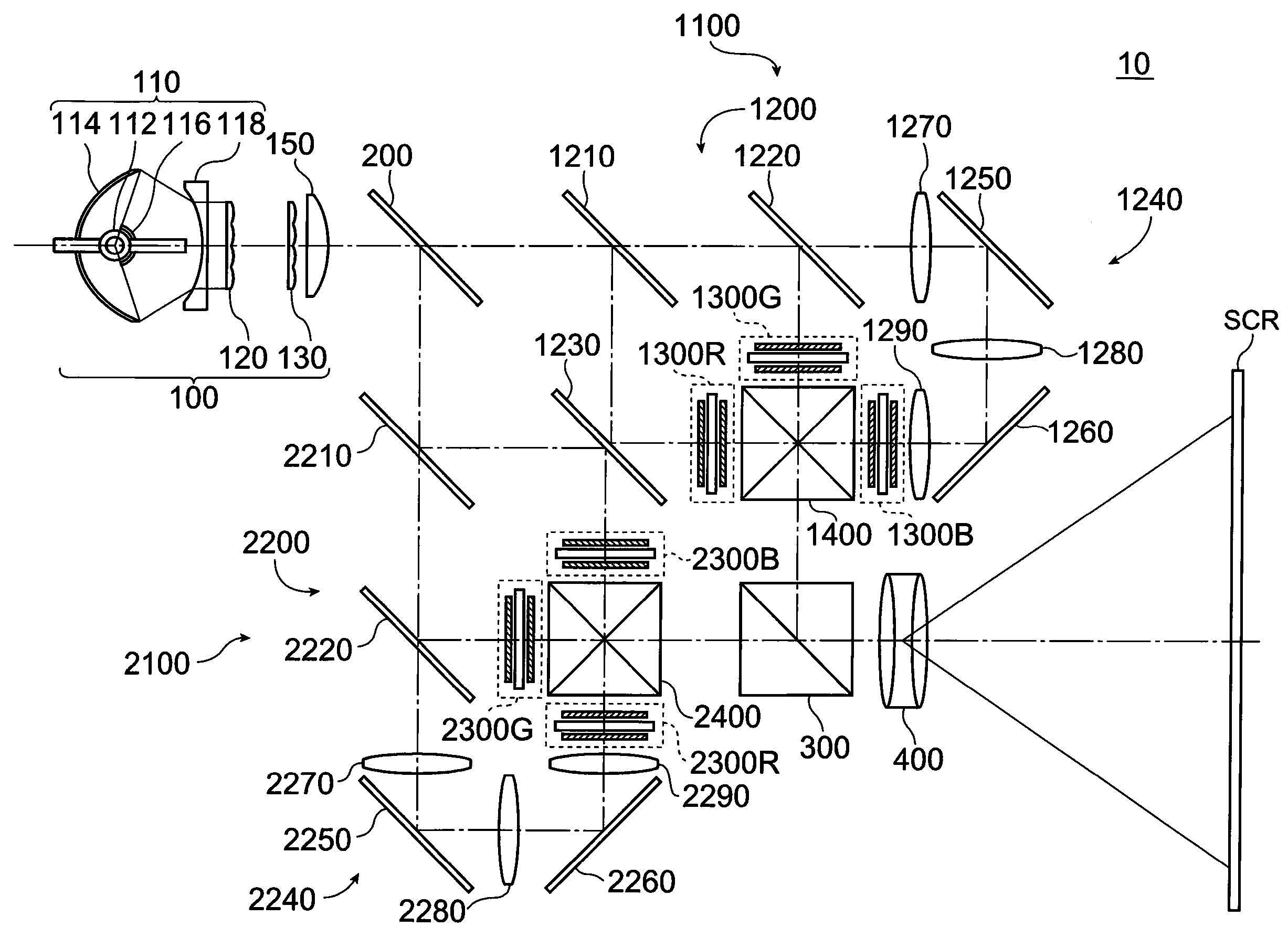
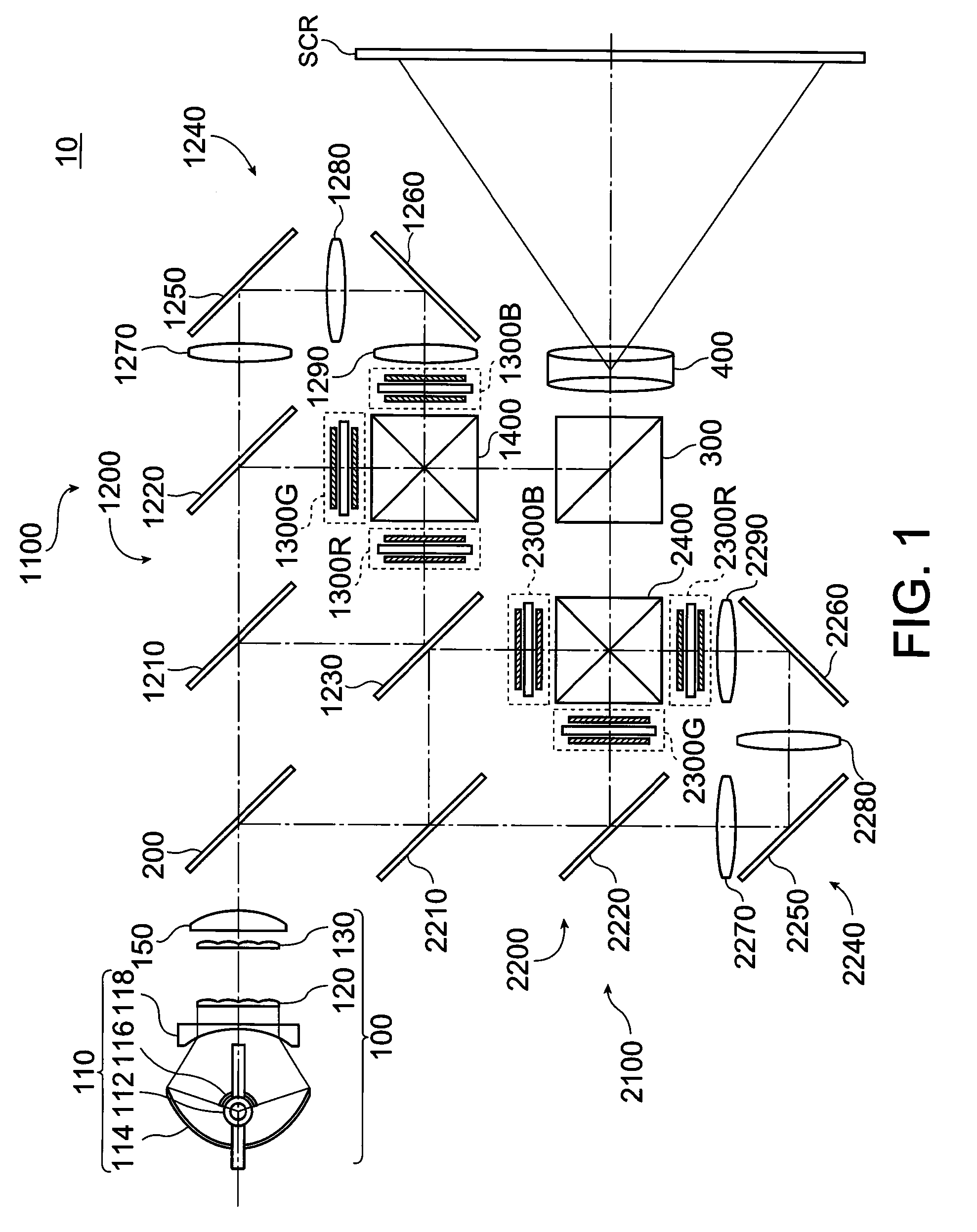
[0066]FIG. 1 diagrammatically shows the optical system of a projector 10 according to a first embodiment. The projector 10 according to the first embodiment includes, as shown in FIG. 1, an illuminator 100 that emits light containing red light (first color light), green light (second color light), and blue light (third color light), a polarization separation mirror 200 as a polarization separation system, a first image formation unit 1100 as first image formation means that outputs first image light, a second image formation unit 2100 as second image formation means that outputs second image light, a polarization combining prism 300 as a polarization combining system, and a projection system 400 that projects image light combined in the polarization combining prism 300.

[0067]The illuminator 100 includes a light source 110 that emits an illumination light flux toward the area to be illuminated, a concave lens 118 disposed on the side of the illuminator 110 that faces the area to be i...

second embodiment

[0111]In the projector 10 according to the first embodiment, the optical system is configured in such a way that for each of the red and blue light, the image light beams corresponding to the same color light beams outputted from the first and second image formation units 1100 and 2100 are reversed from each other in the right-left direction on the projection surface. Alternatively, by carrying out the reverse projection in the right-left direction on the screen SCR described above for the green and the blue light, instead of the red and blue light, an advantage of preventing unevenness in the amount of light in the image projected on the screen SCR is provided.

[0112]FIG. 3 diagrammatically shows the optical system of a projector 20 according to a second embodiment. As shown in FIG. 3, the projector 20 according to the second embodiment has a configuration similar to that shown in FIG. 1 except that the fourth dichroic mirror 2220 serves to reflect the red light and transmit the gre...

third embodiment

[0125]As in the projector 10 according to the first embodiment and the projector 20 according to the second embodiment, when the first image formation unit 1100 and the second image formation unit 2100 share the double-sided reflection mirror 1230, it is preferable to provide an optical axis adjuster for appropriately positioning the optical axes of the color light beams reflected off the reflection surfaces of the double-sided reflection mirror 1230 in the optical systems of the first image formation unit 1100 and the second image formation unit 2100. A projector 30 according to a third embodiment will be described with reference to the case where the optical axis adjuster is a lens for adjusting the optical axis of color light (hereinafter referred to as optical axis adjustment lens).

[0126]FIG. 5 diagrammatically shows the optical system of the projector 30 according to the third embodiment. While the optical system of the projector 30 according to the third embodiment has the sam...


PUM


Abstract

A projector includes a first image formation unit including a first color separation system having a first dichroic mirror that separates the light containing first to third color light components from an illuminator into a light beam containing one of the three color light components and a light beam containing the other two color light components and a second dichroic mirror that separates the light beam that has been separated by the first dichroic mirror and contains the other two color light components, first to third light modulation elements that modulate the first to third color light beams that have been separated by the first color separation system, and a first color combining system that combines image light beams corresponding to the first to third color light beams that have been modulated by the first to third light modulation elements; a second image formation unit including a second color separation system having a third dichroic mirror that separates the light containing the first to third color light components from the illuminator into a light beam containing one of the three color light components and a light beam containing the other two color light components and a fourth dichroic mirror that separates the light beam that has been separated by the third dichroic mirror and contains the other two color light components, fourth to sixth light modulation elements that modulate the first to third color light beams that have been separated by the second color separation system, and a second color combining system that combines image light beams corresponding to the first to third color light beams that have been modulated by the fourth to sixth light modulation elements; a polarization combining system that combines the image light beam outputted from the first image formation unit and the image light beam outputted from the second image formation unit; and a projection system that projects the image light beam that has been combined in the polarization combining system. For each of two color light beams among the first to third color light beams, the image light beams corresponding to the same color light beams outputted from the first and second image formation units are projected in such a way that the image light beams are reversed from each other in the right-left direction on a projection surface.

Description

BACKGROUND[0001]1. Technical Field[0002]The present invention relates to a projector.[0003]2. Related Art[0004]A method has been known in which two projectors are used to project and overlay the same images on one screen (projection surface) (see JP-A-5-107639, for example). According to such a method, the brightness of the projected, overlaid image light is nearly doubled, and hence the image light projected onto the screen is very bright.[0005]In such overlay projection, however, it is not easy to accurately superimpose the image light from the two projectors on the screen. Inaccurate superimposition of the image light from the two projectors degrades the image quality of the projected image.[0006]As a projector of related art capable of solving such a problem, a projector has been proposed which includes a polarization separation system that separates the light from an illuminator into a light beam containing a first polarization component and a light beam containing a second pol...

Claims


Application Information

Patent Timeline
Patent Type & Authority Applications(United States)
IPC IPC(8): G03B21/28
CPCG03B21/00H04N9/3167G03B33/12G03B21/005
Inventor MIYAZAWA, YASUNAGA
Owner SEIKO EPSON CORP
Why Eureka
Try Eureka