Light Recycling in a Micromirror-Based Projection Display System

a technology of projection display and micromirror, which is applied in the field of projector display systems, can solve the problems of inefficiency in light usage in micromirror-based displays, high cost of multiple-modulator display systems, and inefficiency in sequential color display systems, so as to reduce contrast in displayed images, effectively recycle, and efficiently off-pixel light

Active Publication Date: 2009-01-08
TEXAS INSTR INC
View PDF19 Cites 44 Cited by
  • Summary
  • Abstract
  • Description
  • Claims
  • Application Information

AI Technical Summary

Benefits of technology

[0023]It is therefore an object of this invention to provide a micromirror-based display system in which “off” pixel light can be ef

Problems solved by technology

This inefficiency is present not only in single-modulator micromirror-based systems, but also in sequential-color display systems using other types of spatial light modulators (e.g., LCD).
However, the multiple-modulator display system is of course much more expensive, because at least three spatial light modulator chips are required, and because of the complex construction necessary to attain precise alignment and superposition of simultaneously projected image color components.
Another source of inefficiency in light usage is present in micromirror-based displays, as a result of the DMD spatial light modulator reflecting “off” pixel light away from the display screen.
As known in the optics art, this increase in lens size and in back focal distance substantially increases the cost of manufacture of the lenses, especially for relatively “fast” numerical apertures such as f/2.4 and faster.
In addition, the complexity of lens design required for aberration correction also increases with increasing aperture size.
As mentioned above, and as evident from FIG. 2a, the efficiency of conventional micromirror-based display systems is also degraded by the loss of that light that illuminates “off” pixels at the DMD.
However, this known technique has been observed to reduce the contrast of the displayed image, because of the substantial light scattering involved in the redirecting of the “off” pixel light along its same path back to the illumination engine.
Such scattering results from diffraction of the recycled light by the various elements in its return path, as well as diffraction resulting from the inefficiency of anti-reflective coatings at these high angles of incidence.
In addition, DMD 15 itself causes substantial scattering from those individual micromirrors that are in the “on” po

Method used


Image

  • Light Recycling in a Micromirror-Based Projection Display System
  • Light Recycling in a Micromirror-Based Projection Display System
  • Light Recycling in a Micromirror-Based Projection Display System

Examples


Embodiment Construction

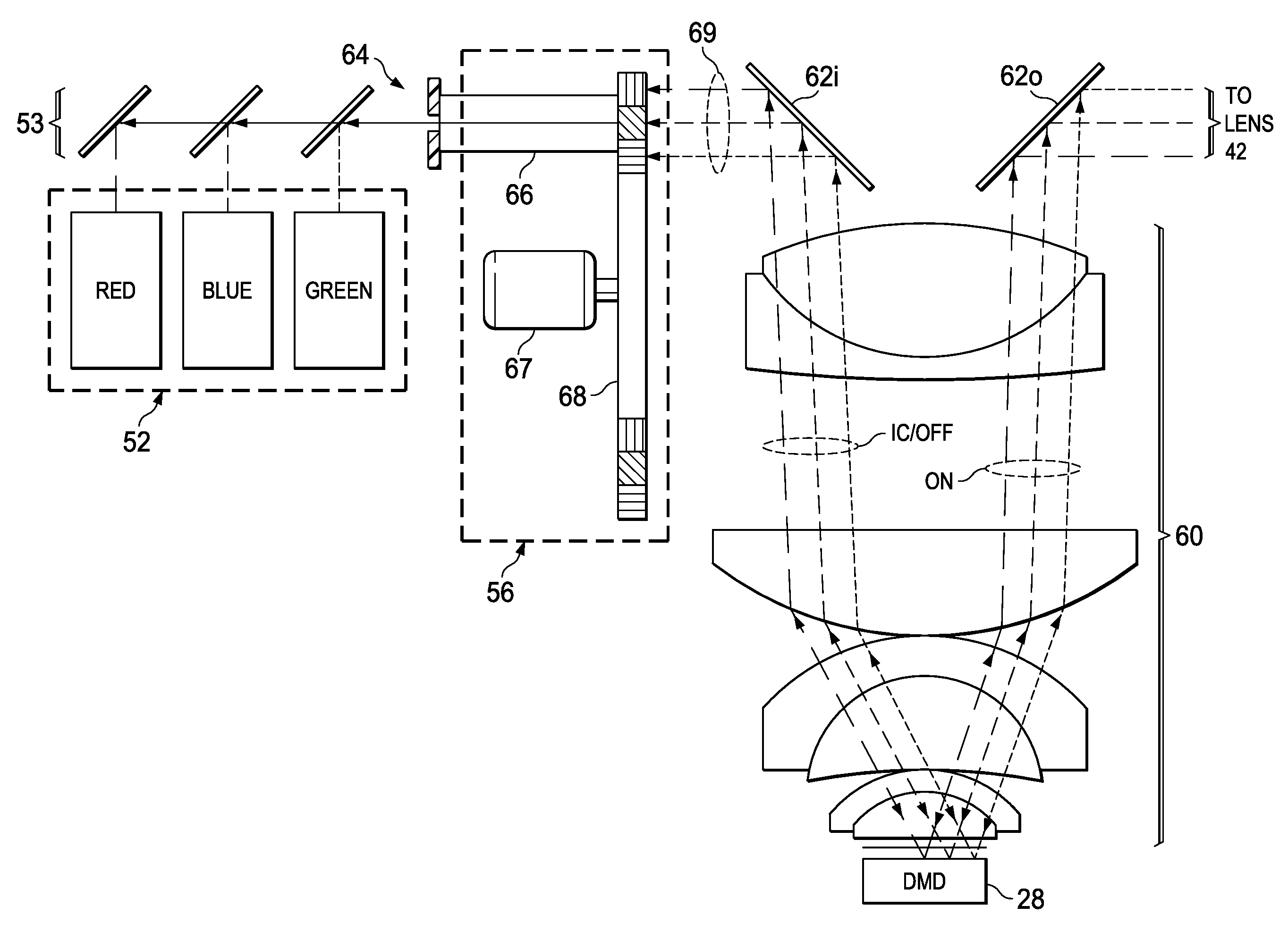
[0041]The present invention will be described in connection with its preferred embodiment, namely as implemented into a rear projection display system utilizing one or more digital micromirror devices as spatial light modulators. However, it is contemplated that this invention may also be beneficial as applied in other types of systems involving digital micromirror devices, as well as other optical systems. Accordingly, it is to be understood that the following description is provided by way of example only, and is not intended to limit the true scope of this invention as claimed.

[0042]FIG. 3 schematically illustrates the functional elements of projection display system 25 according to the preferred embodiments of this invention. The physical arrangement and construction of these elements will be described in further detail below; the illustration of FIG. 3 is presented in a functional manner, to provide functional context for that detailed description.

[0043]As shown in FIG. 3, proj...


PUM


Abstract

A digital micromirror projection display system is disclosed in which “off” pixel light is recaptured and recycled. In the disclosed system, a digital micromirror device directs incident light for “on” pixels in the image to be displayed through projection lenses to a projection screen. The digital micromirror device directs incident light for “off” pixels back toward the light source for recapture by a light integrator. Both the incident and projected light can pass through a rear group of projection lenses, with the first projection lens being disposed near the digital micromirror device. A mirror directs the incident light toward the digital micromirror device, and the “off” pixel light from the digital micromirror device toward the light integrator. As a result, “off” pixel light can be recycled without degrading image contrast, in a manner that can place fast projection lenses close to the digital micromirror device to save cost.

Description

CROSS-REFERENCE TO RELATED APPLICATIONS[0001]This application claims priority, under 35 U.S.C. §119(e), of Provisional Application No. 60 / 947,645, filed Jul. 2, 2007, incorporated herein by this reference.STATEMENT REGARDING FEDERALLY SPONSORED RESEARCH OR DEVELOPMENT[0002]Not applicable.BACKGROUND OF THE INVENTION[0003]This invention is in the field of projection display systems, and is more specifically directed to the recovery of reflected light in a digital micromirror device display system.[0004]As is evident from a visit to a modern electronics store, the number of flat-panel (i.e., non-CRT) televisions has vastly increased in recent years, while the purchase price for such sets continues to fall. This tremendous competition is due in large part to the competing technologies for the display of high-definition television content. As known in the art, three major current display technologies for flat-panel televisions include liquid-crystal display (LCD), plasma display, and dig...

Claims


Application Information

Patent Timeline
IPC IPC(8): G03B21/28
CPCG03B21/28
Inventor DESTAIN, PATRICK R.
Owner TEXAS INSTR INC
Why Eureka
Try Eureka