Circular Dichroism Fluorescent Microscope

a fluorescent microscope and dichroism technology, applied in the field of circular dichroism fluorescent microscope, can solve the problems of inability to analyze such phenomena in a uniform experimental system in a test tube, inability to analyze the chirality of substances that exist in non-uniform environments, and inability to prepare a small amount of biomolecules

Active Publication Date: 2009-01-08
NARA INSTITUTE OF SCIENCE AND TECHNOLOGY
View PDF10 Cites 9 Cited by
  • Summary
  • Abstract
  • Description
  • Claims
  • Application Information

AI Technical Summary

Benefits of technology

[0022]As a result of a diligent study, the inventors of the present invention reached the following findings, and attained the present invention. The inventors found that it is possible to analyze a high-order structure of a sample including a biomolecule (e.g., protein) (i) with the use of a very small amount of the sample and (ii) directly in a living organism, by developing an apparatus that is provide

Problems solved by technology

However, it is impossible to analyze such a phenomenon in a uniform experimental system in a test tube.
Therefore, these techniques are not suitable for analyzing chirality of substances that exist in non-uniform environments, such as in living organisms, where various substances exist.
Moreover, the technique disclosed in each of the Patent Documents 1 and 2 is not directed to a microscope analysis, and requires a large amount of a sample for analysis.
However, generally, only a very small amount of a biomolecule can be prepared.
Accordingly, it takes much time and cost to obtain such a large amount of the sample.
Further, according to the technique disclosed in the Patent Document 3, it is highly likely that measurement is not possible at a practical level.
Particularly, according to the technique disclosed in the Patent Document 3, it is impossible to analyze a sample that emits light whose circularly polarized light component is small.
However, the semi-transmissive mirror (i) lacks wavelength selectivity and (ii) is semi-transmissive.
Thus, a loss of light intensity of the incident excitation light occurs.
Further, a loss of light intensity of the reflected fluorescence light also occurs.
Such losses cause a problem of significant deterioration in measurement accuracy.
Moreover, unless the semi-transmissive mirror is arranged exactly at 45 degrees with respect to a light path, distortion occurs.
This also results in a problem of significant deterioration in measurement accuracy and stability.
This arrangement causes a problem such that an error occurs in detection of a polarized light component of fluorescence light because the fluorescence light that is emitted from the sample is multi-reflected within a polarization modulating section.
However, research and development of such a technique has not been carried out conventionally.

Method used


Image

  • Circular Dichroism Fluorescent Microscope
  • Circular Dichroism Fluorescent Microscope
  • Circular Dichroism Fluorescent Microscope

Examples


reference embodiment 1

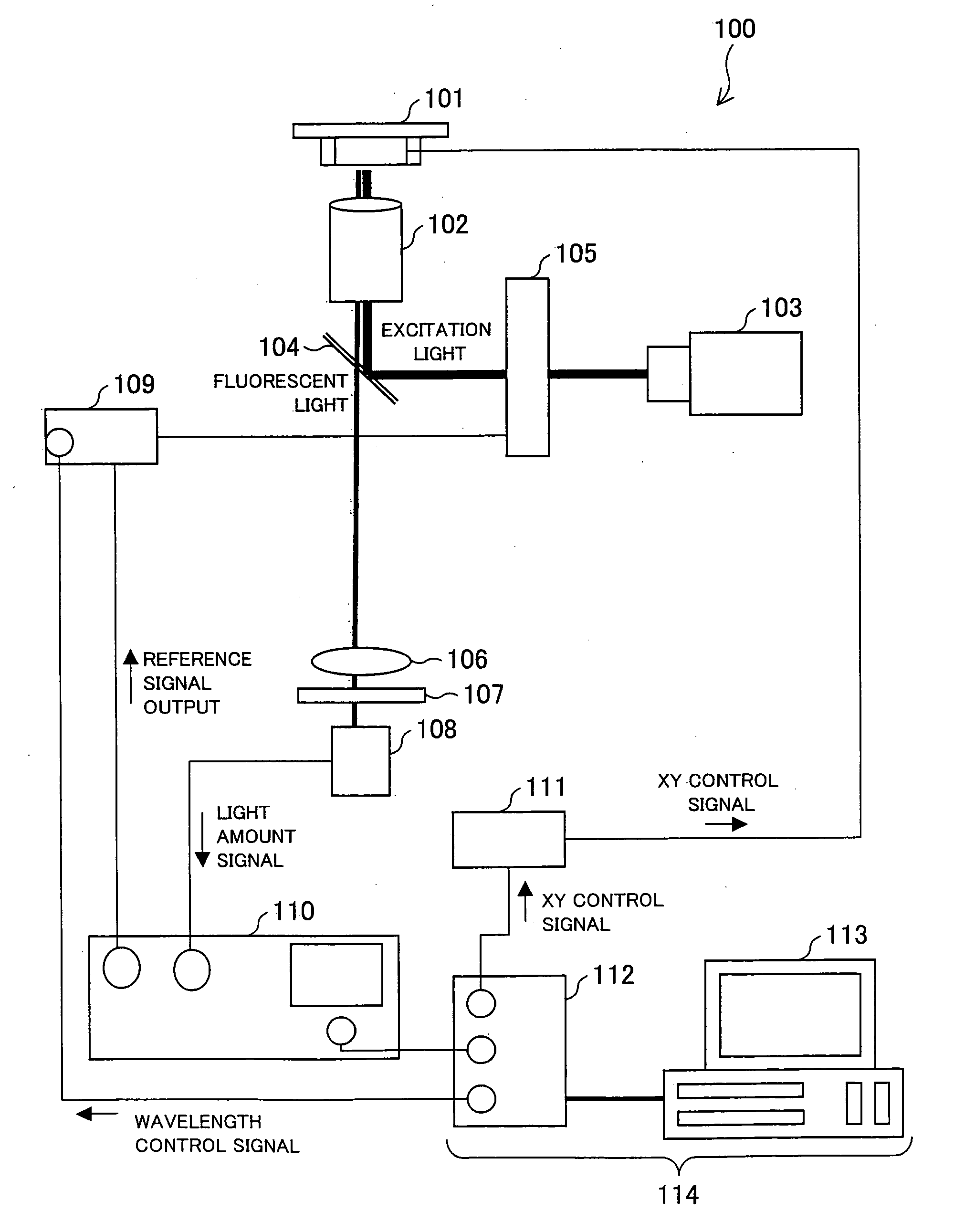
[0075]FIG. 1 is a diagram schematically illustrating a configuration of a circular dichroism fluorescent microscope 100 according to the present Reference Embodiment.

[0076]A circular dichroism fluorescent microscope 100 is a fluorescent microscope apparatus for two-dimensionally analyzing a fluorescence detected circular dichroism (FDCD) spectrum of a sample. Specifically, the circular dichroism fluorescent microscope 100 includes a sample stage 101, an optical lens 102, a light source 103, a wavelength selecting mirror 104, a circular polarizing modulating section 105, an optical lens 106, a wavelength selecting section 107, a fluorescence measuring section 108, a polarization controlling section 109, a detection controlling section 110, a stage controlling section 111, and a signal processing section 114.

[0077]The sample stage 101 is a drive stage that is arranged to be able to move two-dimensionally in XY directions, according to XY control signals from the stage controlling sect...

embodiment 1

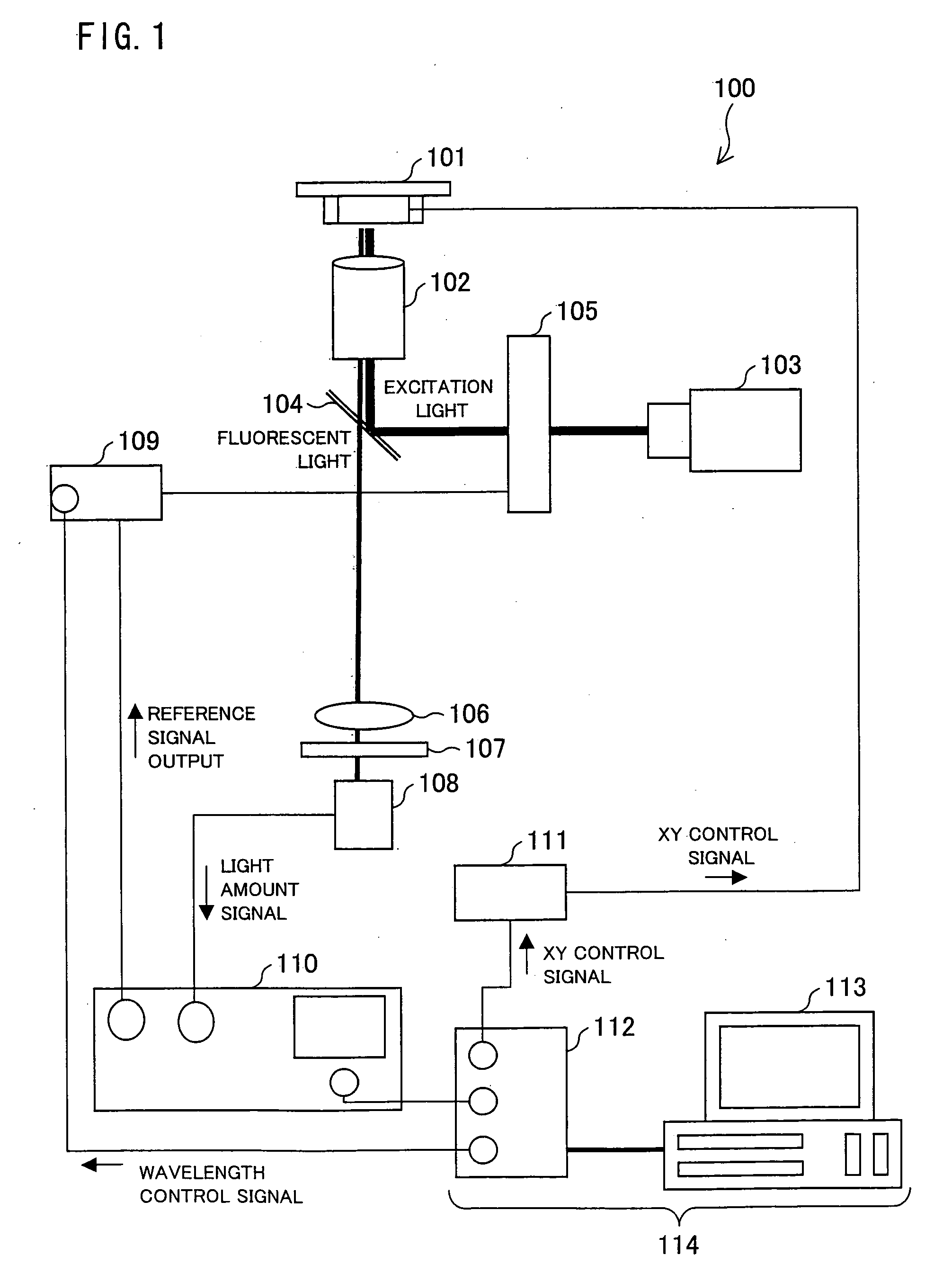
[0108]Reference Embodiment 1 explains one embodiment of a circular dichroism fluorescent microscope for two-dimensionally analyzing a fluorescence detected circular dichroism spectrum. The present embodiment explains one embodiment of a circular dichroism fluorescent microscope that three-dimensionally analyzes a fluorescence detected circular dichroism spectrum by having a confocal microscope configuration. For convenience of an explanation, members having the same functions as those described in Reference Embodiment 1 are given the same reference numerals and the explanations thereof are omitted. The present embodiment explains a difference between the present embodiment and Reference Embodiment 1.

[0109]FIG. 2 is a diagram schematically illustrating a configuration of a circular dichroism fluorescent microscope 100′ in accordance with the present invention.

[0110]The circular dichroism fluorescent microscope 100′ is a fluorescent microscope for three-dimensionally analyzing a fluor...

reference embodiment 2

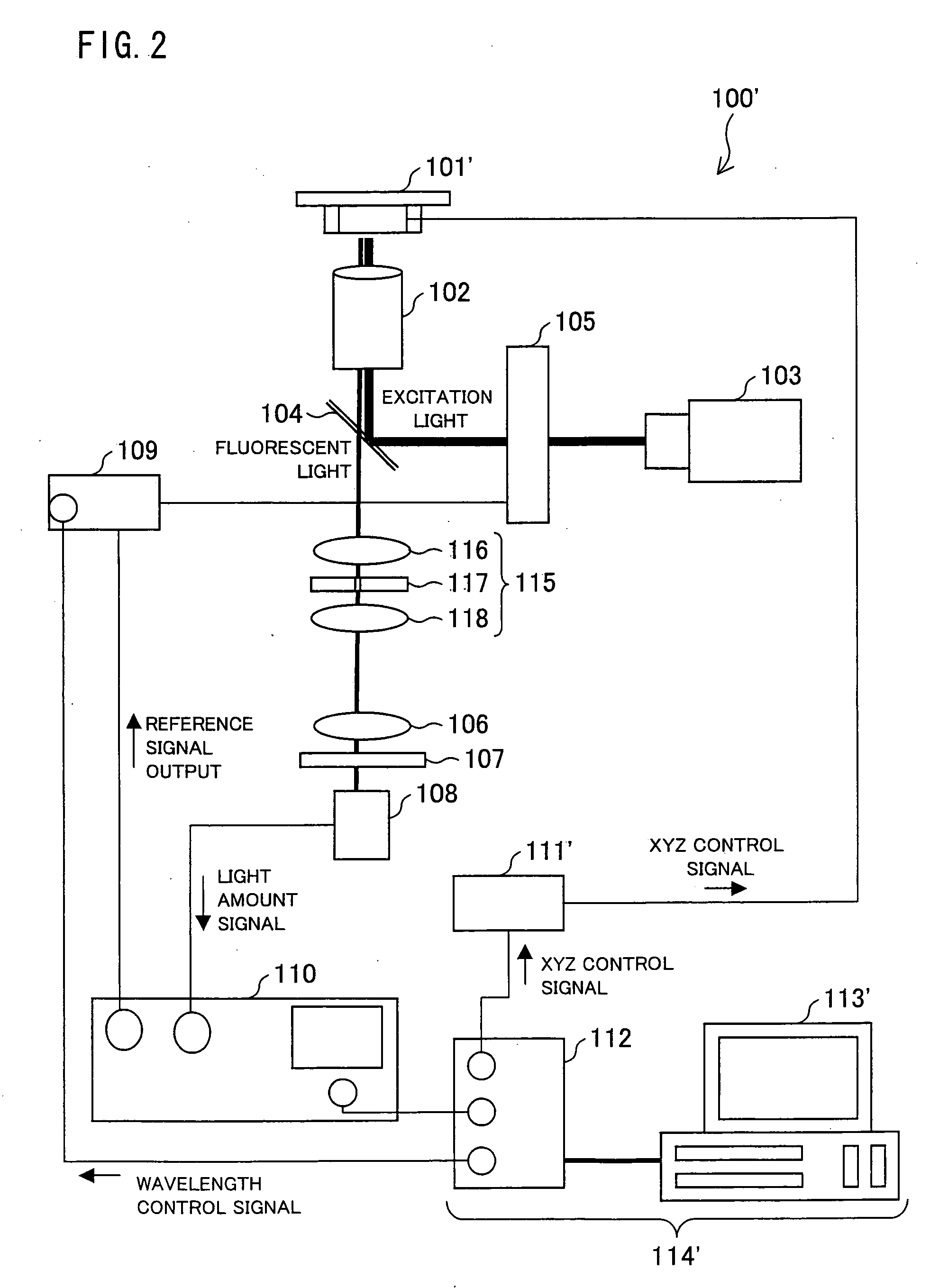
[0118]Each of Reference Embodiment 1 and Embodiment 1 explains one embodiment of a circular dichroism fluorescent microscope for two-dimensionally or three-dimensionally analyzing a fluorescence detected circular dichroism spectrum. The present embodiment explains one embodiment of a circular dichroism fluorescent microscope that can two-dimensionally analyze a circularly polarized luminescence dichroism (CPL) spectrum analysis. For convenience of an explanation, members having the same functions as those described in Reference Embodiment 1 and / or Embodiment 1 are given the same reference numerals, and the explanations thereof are omitted. The present embodiment explains a difference between Reference Embodiment 2 and the above Reference embodiment 1 and / or Embodiment 1.

[0119]FIG. 3 is a diagram schematically illustrating a configuration of a circular dichroism fluorescent microscope 200 in accordance with a present Reference Embodiment. The circular dichroism fluorescent microscope...


PUM


Abstract

According to a circular dichroism fluorescent microscope 100, in one embodiment of the present invention, it is possible to analyze, by using a small amount of a sample and directly in a living organism, a high-order structure of the sample such as a biomolecule, for example, protein and the like. The circular dichroism fluorescent microscope includes a confocal section. In the circular dichroism fluorescent microscope, a circularly polarizing / modulating section converts, into right and left circularly polarized lights, a light beam emitted from a light source. Thus obtained right and left circularly polarized light is focused on the sample so that the sample is irradiated with the right and left circularly polarized lights. Then, an optical lens focuses fluorescence emitted from the sample. Further, a wavelength selecting section transmits only fluorescence having a predetermined wavelength. Subsequently, the fluorescence having passed through the wavelength selecting section is detected. Based on fluorescent intensity signals of the fluorescence thus detected, a difference between an intensity of the fluorescence emitted from the sample at the time of irradiation with the use of the right circularly polarized light and an intensity of the fluorescence emitted from the sample at the time of irradiation with the use of the left circularly polarized light is calculated.

Description

TECHNICAL FIELD[0001]The present invention relates to a circular dichroism fluorescent microscope for observing circular dichroism and, more particularly, relates to a circular dichroism fluorescent microscope for observing a fluorescence detected circular dichroism spectrum or a circularly polarized luminescence dichroism spectrumBACKGROUND ART[0002]Many of physiologically-active substances have so-called chirality. Examples of such physiologically-active substances are a medical substance, a poisonous substance, and a functional component in a living organism. It is widely known that physiological activities of such substances strongly depend on chirality, that is, high-order structures (conformations, configurations, and the like) of the substances. Thus, it is important in a study of physiologically-active substances to understand chirality of the substances. In this regard, chirality and high-order structures of biomolecules including protein, nucleic acid, and the like, in par...

Claims


Application Information

Patent Timeline
IPC IPC(8): G01N21/64G02B21/06
CPCG01N21/19G02B21/16G01N21/6458G01N21/6445
Inventor KAWAI, TSUYOSHIKAWAMURA, KENSUKE
Owner NARA INSTITUTE OF SCIENCE AND TECHNOLOGY
Why Eureka
Try Eureka