Vehicle and method of determining whether or not to stop engine mounted in vehicle

a technology of engine and vehicle, which is applied in the direction of position fixation, special data processing applications, navigation instruments, etc., can solve the problems of difficult to determine whether or not to stop the engine by an ecu and difficult to determine whether or not to stop the engine only based on the signal from the tilting sensor

Active Publication Date: 2009-01-08
KAWASAKI MOTORS LTD
View PDF10 Cites 18 Cited by
  • Summary
  • Abstract
  • Description
  • Claims
  • Application Information

AI Technical Summary

Benefits of technology

[0005]The present invention addresses the above described condition, and an object of the present invention is to provide a vehicle which is capable of determining whether or not to stop an engine precisely, depending on a driving state of the vehicle.

Problems solved by technology

In such a case, it is difficult for an ECU to determine whether or not to stop the engine, based only on a signal from a tilting sensor that detects that the vehicle body is tilted.
In this case, it is not necessary to stop the engine, but it is difficult to determine whether or not to stop the engine only based on the signal from the tilting sensor.

Method used


Image

  • Vehicle and method of determining whether or not to stop engine mounted in vehicle
  • Vehicle and method of determining whether or not to stop engine mounted in vehicle
  • Vehicle and method of determining whether or not to stop engine mounted in vehicle

Examples


embodiment 1

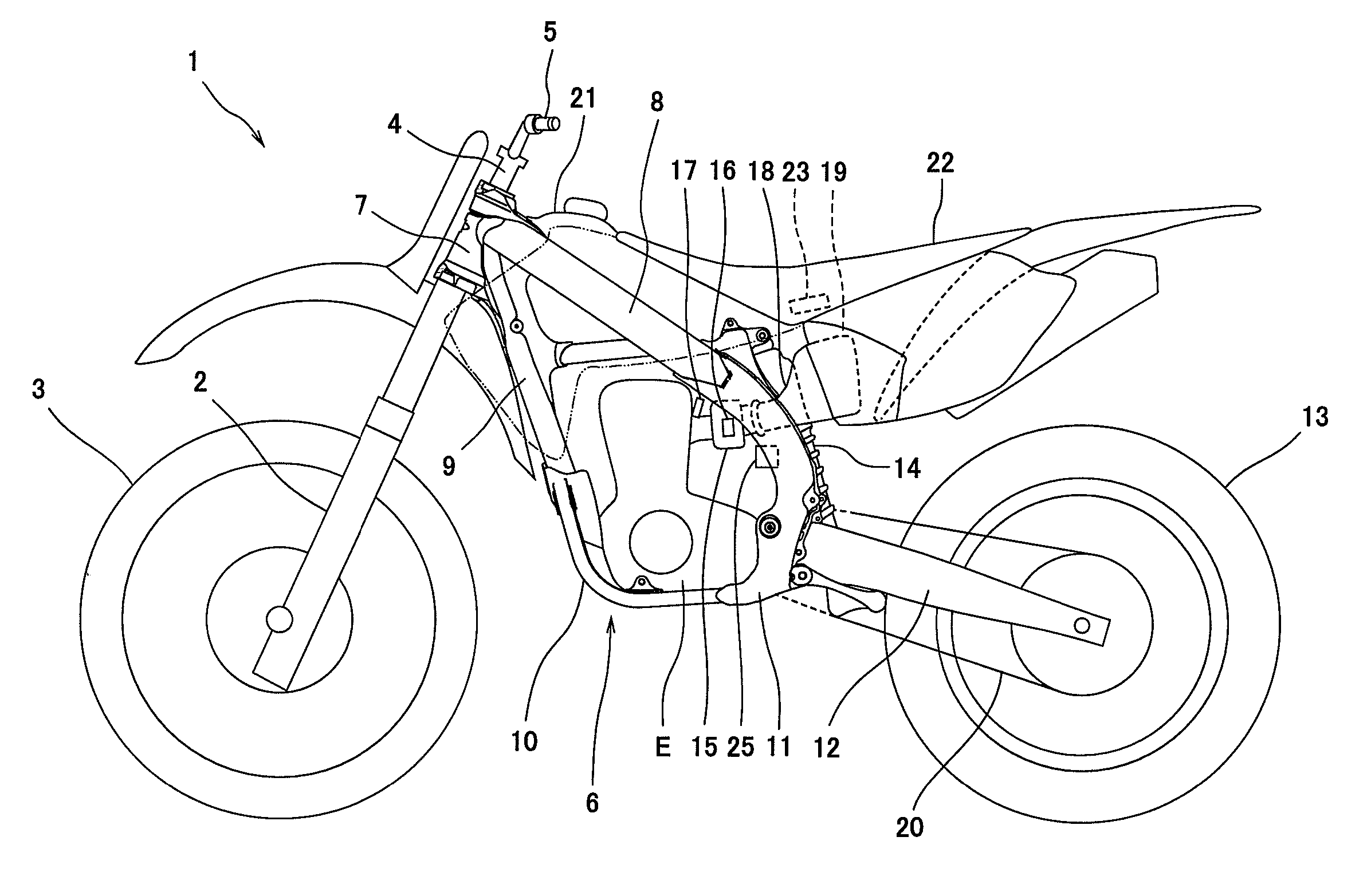
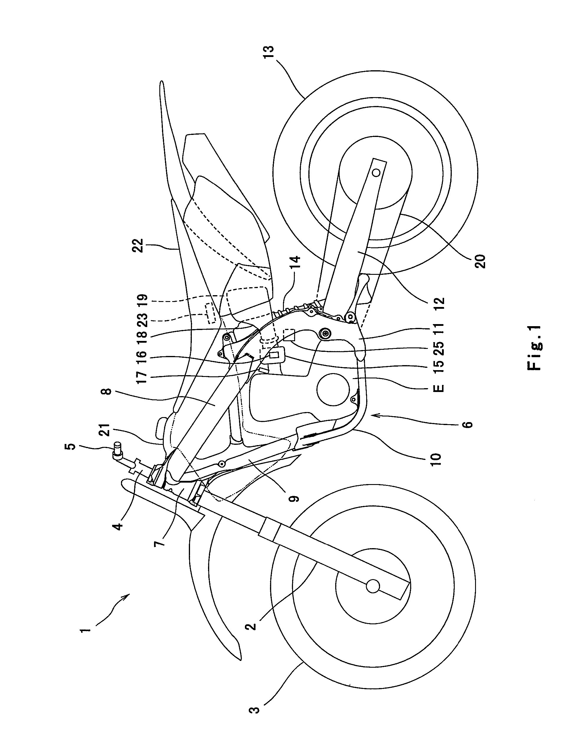
[0046]FIG. 1 is a side view of a motorcycle 1 according to a first embodiment of the present invention. As shown in FIG. 1, the motorcycle 1 is an off-road motorcycle. The motorcycle 1 includes a front fork 2 extending substantially vertically to have a specified caster angle, and a front wheel 3, which is a steering wheel and is rotatably mounted to a lower end portion of the front fork 2. The front fork 2 is mounted at an upper portion thereof to a lower bracket and an upper bracket which are not shown. A bar-type steering handle 5 is attached to a handle support portion 4 on an upper part of the upper bracket. A steering shaft (not shown) is rotatably mounted by a head pipe 7 forming a frame 6. A driver rotates the steering handle 5 to the right or to the left, thereby steering the front wheel 3.

[0047]The frame 6 includes the head pipe 7, and a pair of right and left main pipes 8 extending rearward from an upper portion of the head pipe 7 so as to be tilted slightly in a downward...

embodiment 2

[0057]FIG. 6 is a block diagram showing an engine stop system 40 of a motorcycle according to a second embodiment of the present invention. In FIG. 6, the same reference numerals as those in the first embodiment denote the same or corresponding parts which will not be further described in the second embodiment. Turning to FIG. 6, the engine stop system 40 includes the tilting sensor 25, an engine speed sensor 41, a clutch switch 42, a brake switch 43, a gear position sensor 44, an acceleration sensor 45, a vehicle speed sensor 46, a GPS sensor 47, a grip pressure-sensitive switch 48, an ECU 50, and the fuel injector 17.

[0058]The engine speed sensor 41 is a crank angle sensor coupled to a crankshaft of the engine E (see FIG. 1) and is configured to be able to detect an engine speed of the engine E which is obtained by calculation of a change amount of a crank angle of the crankshaft per unit time in the ECU 50. The clutch switch 42 is configured to detect an ON operation and an OFF o...

embodiment 3

[0071]FIG. 8 is a block diagram showing an engine stop system 60 of a motorcycle according to a third embodiment of the present invention. In FIG. 8, the same reference numerals as those in the first embodiment denotes the same or corresponding parts which will not be further described in the third embodiment. Turning to FIG. 8, the engine stop system 60 includes the tilting sensor 25, a suspension stroke sensor 61, an ECU 62 and the fuel injector 17. The suspension stroke sensor 61, which serves as the driving state sensor, is configured to detect an extended state and a contracted state, i.e., a suspension stroke amount of the rear suspension 14 which serves to absorb an impact applied to the motorcycle. For example, the suspension stroke sensor 61 may be a displacement sensor configured to detect a distance between an upper position and a lower position of the rear suspension 14, which is substantially vertically displaceable.

[0072]The ECU 62 is configured to control the fuel inj...


PUM


Abstract

A vehicle including an engine, a tilting sensor configured to detect that a vehicle body of the vehicle has been tilted a predetermined angle or larger, a driving state sensor configured to detect a driving state of the vehicle using a component other than the tilting sensor, and a determiner configured to determine whether or not to stop the engine, based on a signal received from the tilting sensor, and a signal received from the driving state sensor.

Description

TECHNICAL FIELD[0001]The present invention relates to a vehicle equipped with an engine, such as a motorcycle, a three-wheeled or four-wheeled all terrain vehicle, or personal watercraft (PWC), and a method of determining whether or not to stop the engine mounted in the vehicle.BACKGROUND ART[0002]In vehicles equipped with conventional fuel injection systems (FI systems), an ECU (electronic control unit) causes a fuel injector to inject a predetermined amount of fuel to an interior of an air-intake passage connected to an engine. In a such a fuel injection type vehicle, a tilting sensor detects that a body of the vehicle is tilted, and the ECU causes the fuel injector to stop fuel injection, thereby forcibly stopping the engine, when the tilting sensor detects that the body is tilted a specified angle or larger.[0003]Riders often jump motocross motorcycles when traveling over bumpy mountain roads or when traveling off-road. In such circumstances, a rider may intentionally tilt a veh...

Claims


Application Information

Patent Timeline
Patent Type & Authority Applications(United States)
IPC IPC(8): B60G17/016
CPCF02D17/04B60W2520/16F02D2200/701B60K28/14F02D41/042B60Y2200/12
Inventor KAWAMURA, NAOKITAMURA, JUNJIOGINO, TAKAHIROKAI, SEIICHIKAWASETSU, SHINTA
Owner KAWASAKI MOTORS LTD
Why Eureka
Try Eureka