
Sound source separation apparatus and sound source separation method

Inactive Publication Date: 2009-01-08
KOBE STEEL LTD +1
View PDF3 Cites 53 Cited by
  • Summary
  • Abstract
  • Description
  • Claims
  • Application Information

AI Technical Summary

Benefits of technology

[0008]It is therefore an object of the invention to provide a sound source separation apparatus and a sound source separation method that can provide a high sound source separation performance even under an environment where a bias in positions of sound sources with respect to a plurality of microphones can occur.
[0020]performing, on one signal in the specific SIMO signal, a process of comparing volumes of the specific beamformer processed sound signal and the intermediate processed signal according to each of the plurally sectioned frequency components and, when a comparison result meets a predetermined condition, of eliminating a signal of the corresponding frequency component, and

Problems solved by technology

However, there is a problem that, when the BSS based on the ICA method, which makes note of the independency of the sound source signals (individual sound signals), is used in an actual environment, sound signal components from sound sources other than a specific sound source become mixed in a separated signal due to effects of sound signal transmission characteristics, etc.
Also, with the sound source separation process by the binaural signal process, because the sound source separation process is performed by comparing the volume levels of each of the plurally sectioned frequency components (frequency bins), the sound source separation process performance is poor when there is a bias in the positions of the sound sources with respect to the plurality of microphones.
For example, when the plurality of sound sources are concentrated in a sound collection region of a certain directional stereo microphone, the sound source separation process cannot be correctly performed.

Method used


Image

  • Sound source separation apparatus and sound source separation method
  • Sound source separation apparatus and sound source separation method
  • Sound source separation apparatus and sound source separation method

Examples


first embodiment

See FIG. 1

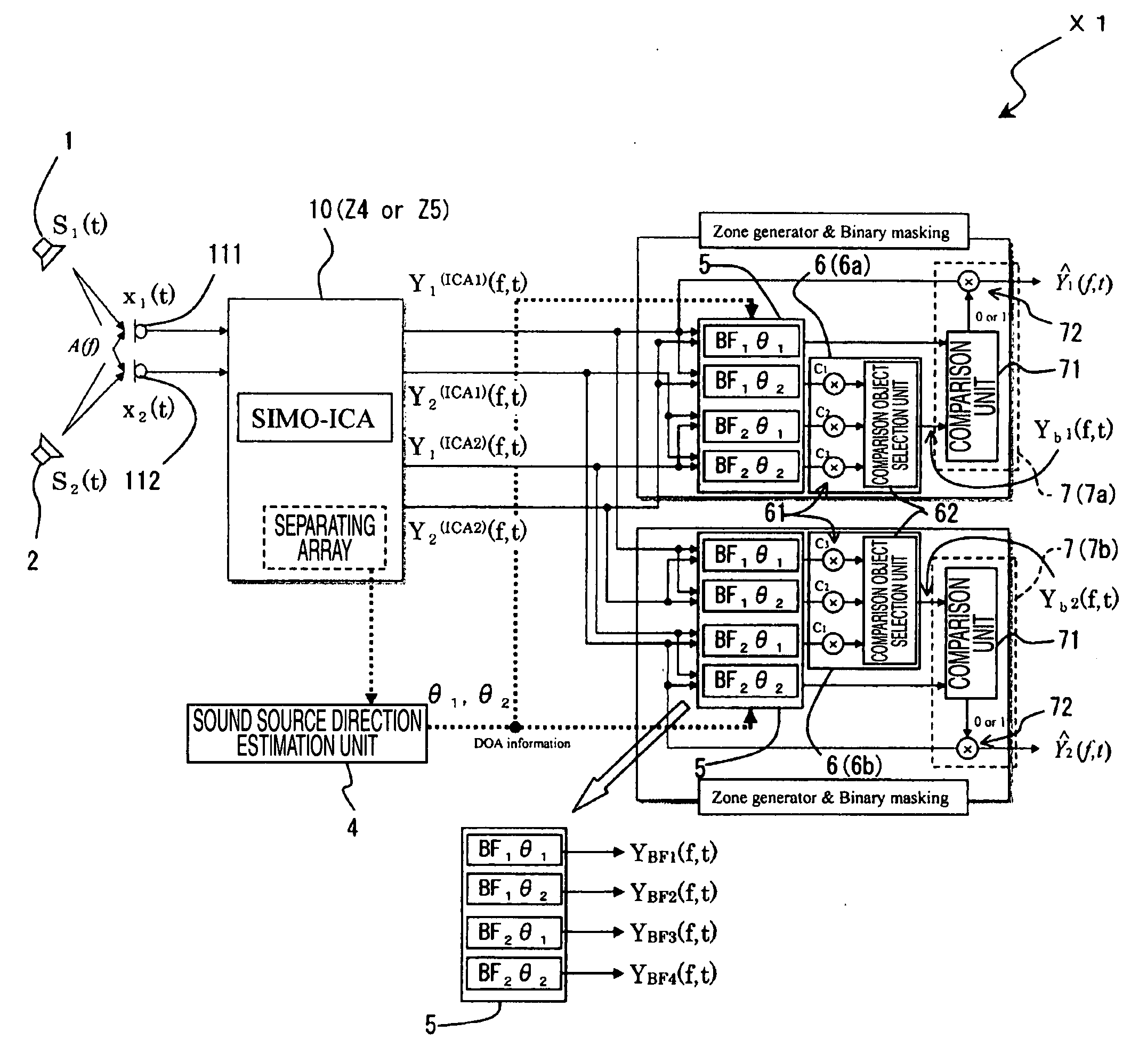
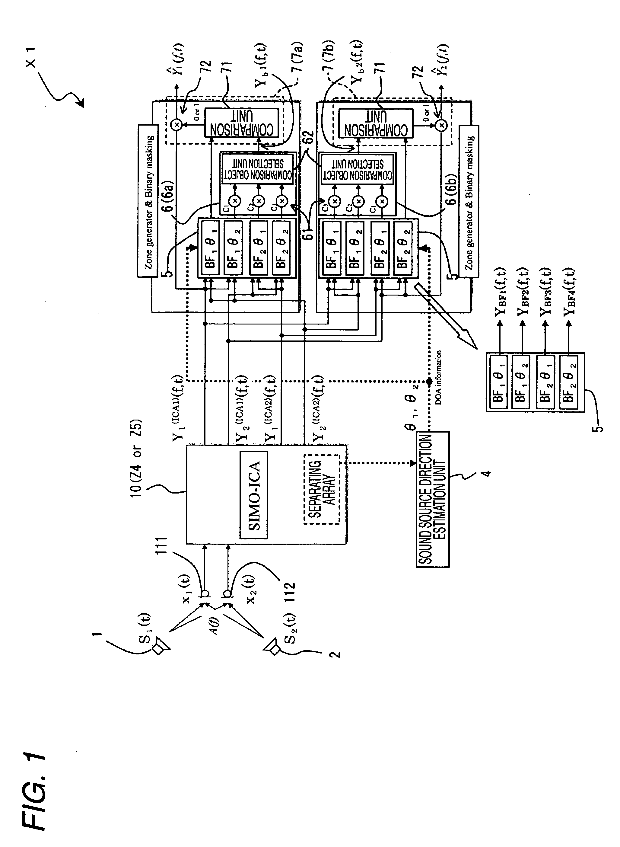
[0086]A sound source separation apparatus X1 according to the first embodiment of the present invention shall now be described using a block diagram shown in FIG. 1.

[0087]The sound source separation apparatus X1 generates and outputs a separated signal by separating (extraction) at least one sound source signal (individual sound signal) from a plurality of mixed sound signals Xi(t), which, in a state where a plurality of sound sources 1 and 2 and a plurality of microphones 111 and 112 are present in a certain acoustic space, are respectively inputted through the plurality of microphones 111 and 112 and in which the respective sound source signals (individual sound signals) from the plurality of sound sources 1 and 2 are superimposed. Separated signals Y1(ICA1)(f, t), Y2(ICA1)(f, t), Y1(ICA2)(f, t), and Y2(ICA2)(f, t) in FIG. 1 respectively correspond to the separated signal y11(f), y22(f), y21(f), and y12(f) in FIGS. 6 and 7. Here, the plurality of microphones 111 and 112 ...

second embodiment

See FIG. 2

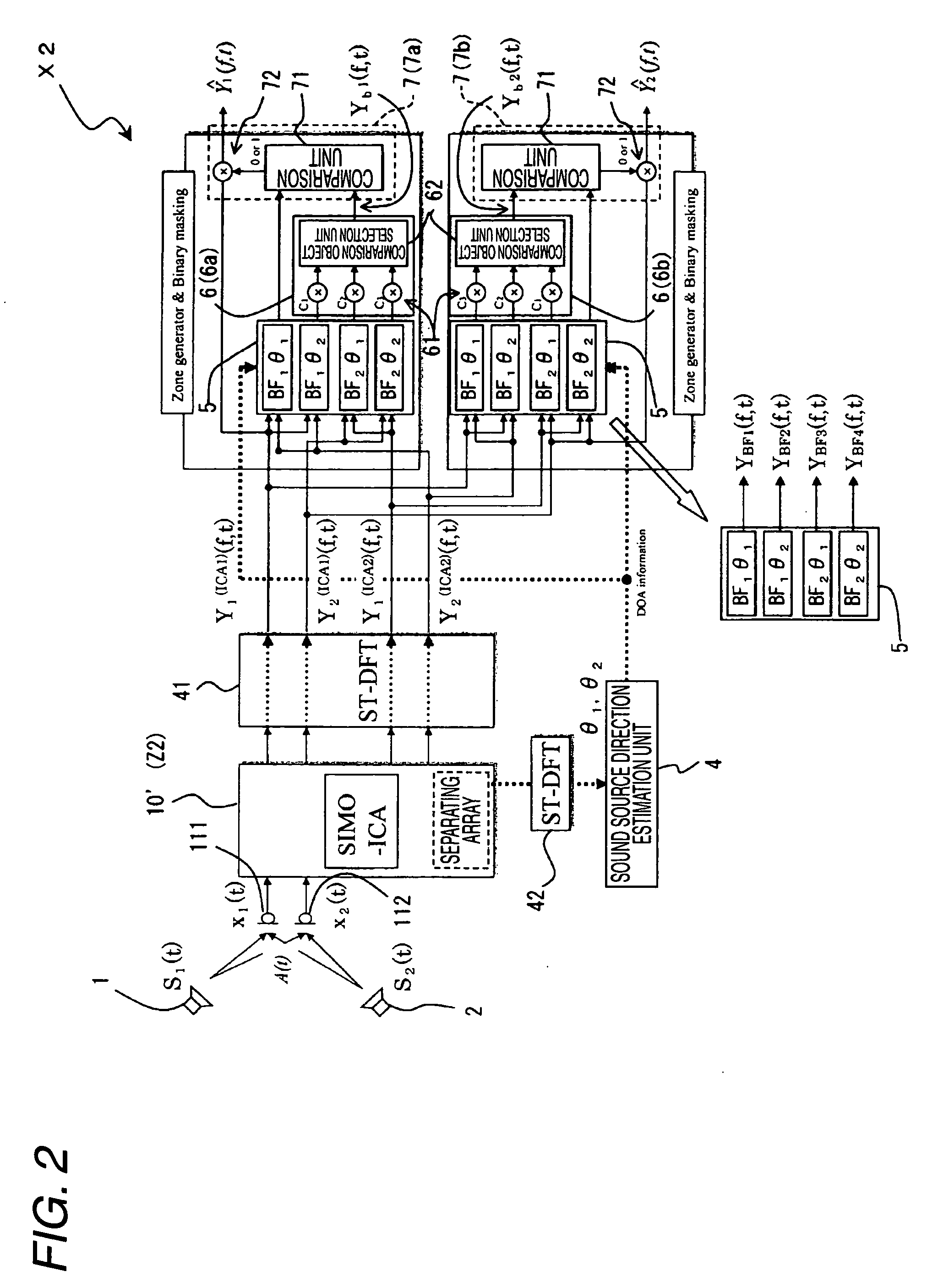
[0164]A sound source separation apparatus X2 according to a second embodiment of the present invention shall nowbe described with reference to a block diagram shown in FIG. 2.

[0165]The sound source separation apparatus X2 has basically the same arrangement as the sound source separation apparatus X1, and only the points of difference with respect to the sound source separation apparatus X1 shall be described below. In FIG. 2, components that are the same as those of FIG. 1 are provided with the same symbols.

[0166]With the sound source separation apparatus X2, the SIMO-ICA process unit 10 (employing the sound source separation apparatus Z4 or Z5 that performs the SIMO-ICA process in the frequency domain) in the sound source separation apparatus X1 is replaced by an SIMO-ICA process unit 10′ employing the sound source separation apparatus Z2 that performs the sound source separation process based on the TD-SIMO-ICA method (SIMO-ICA process in the time domain).

[0167]The separ...


PUM


Abstract

A sound source separation apparatus includes: an SIMO-ICA process unit, separating and generating an SIMO signal by the BSS method based on the ICA method; a sound source direction estimation unit, estimating a sound source direction based on a separating matrix, computed by a learning calculation of the BSS method based on the ICA method; a beamformer process unit, performing, on each SIMO signal, a beamformer process of enhancing, according to each frequency bin, a sound component from each sound source direction; an intermediate process unit, performing an intermediate process that includes performing a selection process, etc., according to each frequency bin on signals other than a specific signal among the beamformer processed sound signals; and an untargeted signal component elimination unit, eliminating noise signal components by comparing for one signal in the specific SIMO signal, volumes of the specific beam former processed sound signal and the intermediate processed signal according to each frequency bin.

Description

BACKGROUND OF THE INVENTION[0001]The present invention relates to a sound source separation apparatus and a sound source separation method for identifying (separating) at least one individual sound signal from a plurality of mixed sound signals, which, in a state where a plurality of sound sources and a plurality of sound input means are present in a predetermined acoustic space, are respectively inputted through the plurality of sound input means and in which are superimposed the respective individual sound signals from the plurality of sound sources.[0002]When a plurality of sound sources and a plurality of microphones (sound input means) are present in a predetermined acoustic space, sound signals (referred to herein after as “mixed sound signals”), in which are superimposed respective individual sound signals (referred to herein after as the “sound source signals”) from the plurality of sound sources, are respectively acquired through the plurality of microphones. A method for p...

Claims


Application Information

Patent Timeline
IPC IPC(8): G10L21/00G10L21/0272G10L21/028
CPCH04R1/403G10L21/0272
Inventor IKEDA, YOHEIHIEKATA, TAKASHIMORITA, TAKASHISARUWATARI, HIROSHIMORI, YOSHIMITSU
Owner KOBE STEEL LTD
Features
  • Generate Ideas
  • Intellectual Property
  • Life Sciences
  • Materials
  • Tech Scout
  • Unparalleled Data Quality
  • Higher Quality Content
  • 60% Fewer Hallucinations
Learn More