Buffer insertion to reduce wirelength in VLSI circuits

a buffer and wire length technology, applied in the direction of instruments, geometric cad, computing, etc., can solve the problems of large number of cells, difficult physical design without the aid of computers, and complicated connections between cells

Inactive Publication Date: 2009-01-08
GLOBALFOUNDRIES INC
View PDF2 Cites 6 Cited by
  • Summary
  • Abstract
  • Description
  • Claims
  • Application Information

AI Technical Summary

Benefits of technology

[0014]It is another object of the present invention to provide such a method which reduces wirelength.
[0015]It is yet another object of the present invention to provide an improved method of buffer insertion which improves routability and saves power.

Problems solved by technology

An IC may include a very large number of cells and require complicated connections between the cells.
Due to the large number of components and the details required by the fabrication process for very large scale integrated (VLSI) devices, physical design is not practical without the aid of computers.
As process technology scales to the submicron regime, interconnect delays increasingly dominate gate delays.
Therefore, both the complexity and importance of buffer insertion is increasing in an even faster pace.
However, physical synthesis can take days to complete.
Increasing the frequency of buffer insertion locations can improve timing of the net, but at an increased buffer cost.
During physical synthesis, nets can become inefficiently wired for many reasons, such as placement, legalization around blockages, or area-driven buffer insertion.
Inefficient wire placement can adversely affect routability and can also waste power, which is an increasing problem with more resistive wiring.

Method used


Image

  • Buffer insertion to reduce wirelength in VLSI circuits
  • Buffer insertion to reduce wirelength in VLSI circuits
  • Buffer insertion to reduce wirelength in VLSI circuits

Examples


Embodiment Construction

)

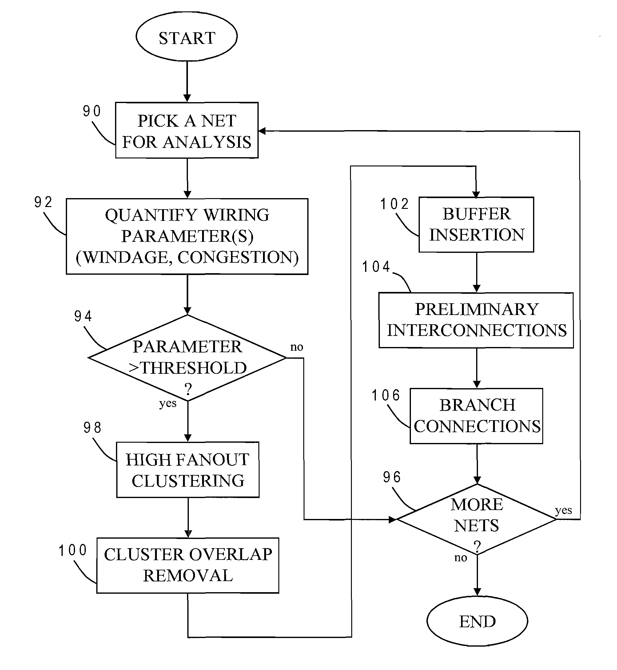
[0030]The present invention provides a novel method for determining buffer insertion locations in a net of an integrated circuit design, and is generally applicable to any type of IC design, such as general-purpose microprocessors, memory units or special-purpose circuitry. The method may be implemented as part of a physical synthesis process which optimizes placement, timing, power consumption, crosstalk effects or other design parameters. As explained more fully below, exemplary embodiment of the present invention utilizes high fanout clustering of net sinks and rewired buffers to produce a more efficient buffered wirelength.

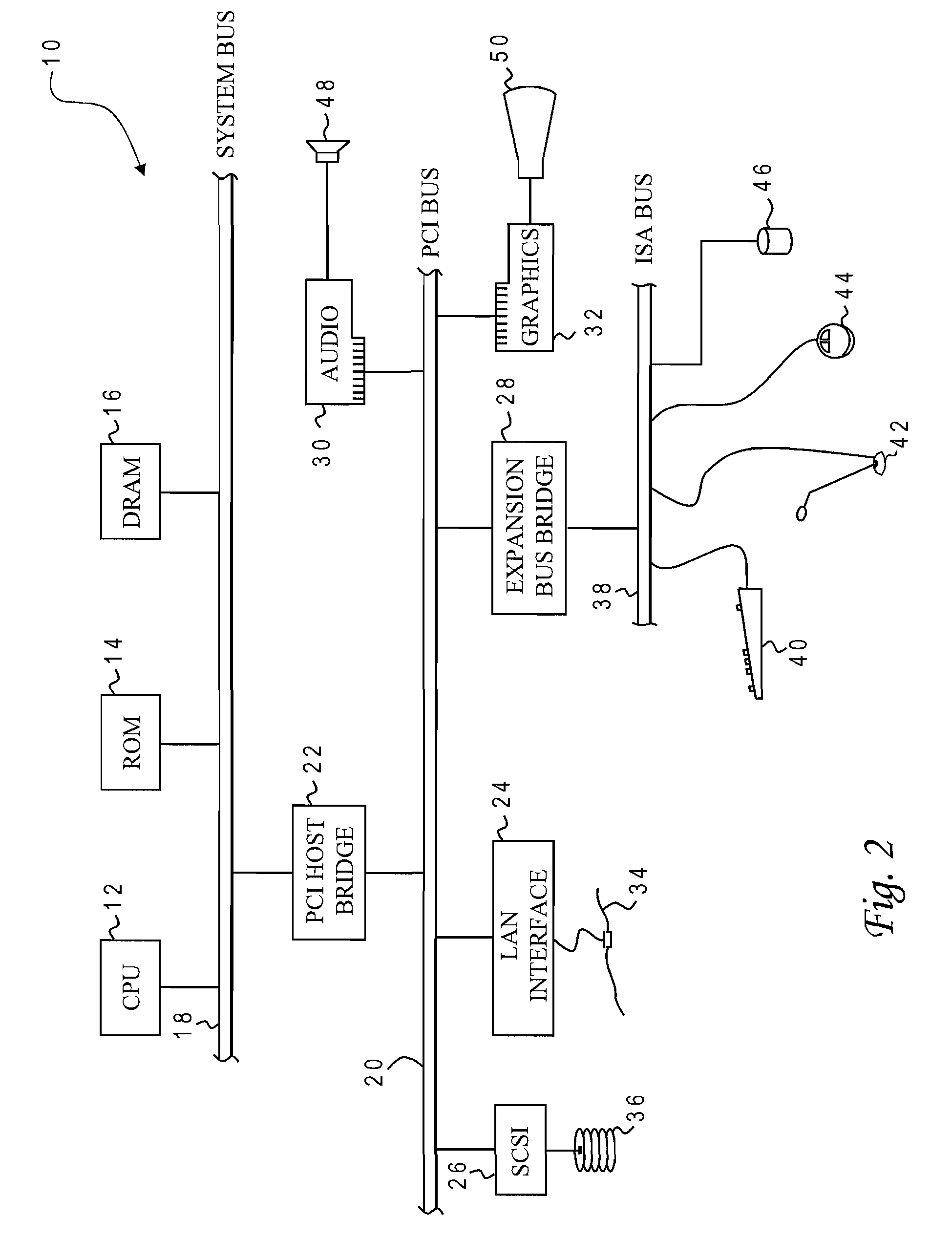
[0031]With reference now to the figures, and in particular with reference to FIG. 2, there is depicted one embodiment 10 of a computer system programmed to carry out the buffer insertion in accordance with one implementation of the present invention. System 10 includes a central processing unit (CPU) 12 which carries out program instructions, firmware or read...


PUM


Abstract

Wirelength in a net of an integrated circuit design is reduced by forming clusters of sinks to be interconnected, inserting a buffer at each cluster, and providing branch connections between clusters by connecting a sink of one cluster to a buffer of another cluster, to create a buffer tree spanning all sinks. The buffers are inserted at a point on a respective bounding box of a cluster that is closest to a source for the net. A sink that provides a branch connection to the buffer of another cluster is the closest sink to that buffer (except for those sinks in the cluster). Clusters may be formed by examining different pairs of the sinks with different bounding boxes, and identifying one of the pairs whose bounding box has a lowest half-perimeter as the best pair for clustering.

Description

CROSS-REFERENCE TO RELATED APPLICATION[0001]This application is a continuation of copending U.S. patent application Ser. No. 11 / 383,544 filed May 16, 2008.BACKGROUND OF THE INVENTION[0002]1. Field of the Invention[0003]The present invention generally relates to the fabrication and design of semiconductor chips and integrated circuits, specifically to a method of designing the physical layout (placement) of logic cells in an integrated circuit and the wiring (routing) of those cells, and more particularly to the use of buffer insertion to manage timing and electrical requirements in an integrated circuit design.[0004]2. Description of the Related Art[0005]Integrated circuits are used for a wide variety of electronic applications, from simple devices such as wristwatches, to the most complex computer systems. A microelectronic integrated circuit (IC) chip can generally be thought of as a collection of logic cells with electrical interconnections between the cells, formed on a semicond...

Claims


Application Information

Patent Timeline
Patent Type & Authority Applications(United States)
IPC IPC(8): G06F17/50
CPCG06F2217/84G06F17/509G06F30/18G06F2119/12
Inventor ALPERT, CHARLES J.MAHMUD, TUHINQUAY, STEPHEN T.
Owner GLOBALFOUNDRIES INC
Why Eureka
Try Eureka