Manifold communication channel

a communication channel and multiple channel technology, applied in the field of internal combustion engines, can solve the problems of increasing engine emissions, preventing the process, and consuming a lot of wet fuel from multiple cylinder barrels, and achieve the effect of engine power enhancemen

Active Publication Date: 2009-01-15
KOHLER CO
View PDF22 Cites 17 Cited by
  • Summary
  • Abstract
  • Description
  • Claims
  • Application Information

AI Technical Summary

Benefits of technology

[0010]More particularly, given the location of a communication channel in this manner, charge can still proceed between the different barrels / intake tubes, and thus charge from multiple carburetor barrels can still proceed to a given cylinder. At the same time, because the communication channel does not link the lower portions of the barrels / intake tubes, wet fuel arising from a given carburetor barrel is largely or entirely precluded from proceeding to a cylinder associated with a different carburetor barrel, and consequently excessive amounts of wet fuel from multiple cylinder barrels are largely if not entirely prevented from proceeding to any single cylinder where the wet fuel might not properly be consumed. Further, while such a communication channel can be limited in terms of its width, and in particular have a width less than the width of the barrels or intake tubes that it is connecting, by extending the depth of the communication channel along the intake tubes (e.g., in the direction of flow through those tubes), it is still possible for significant amounts of charge to pass between neighboring intake tubes, and thus possible for significant engine power enhancements to be achieved.

Problems solved by technology

The present inventors have recognized that the conventional manner of implementing communication channels to link the multiple barrels of multi-barrel carburetors in multi-cylinder engines results in increased engine emissions at least in part because the output of charge by carburetors tends to be accompanied by the output of amounts of unevaporated fuel or “wet fuel”, because such wet fuel is able to proceed in excessive amounts to a given engine cylinder when a communication channel linking multiple carburetor barrels is present, and because these amounts of wet fuel often are not adequately consumed during combustion.
At the same time, because the communication channel does not link the lower portions of the barrels / intake tubes, wet fuel arising from a given carburetor barrel is largely or entirely precluded from proceeding to a cylinder associated with a different carburetor barrel, and consequently excessive amounts of wet fuel from multiple cylinder barrels are largely if not entirely prevented from proceeding to any single cylinder where the wet fuel might not properly be consumed.

Method used


Image

  • Manifold communication channel
  • Manifold communication channel
  • Manifold communication channel

Examples


Embodiment Construction

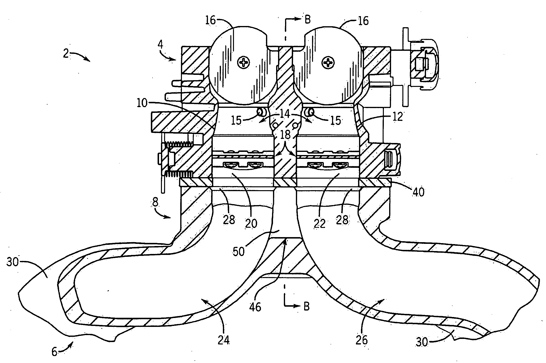
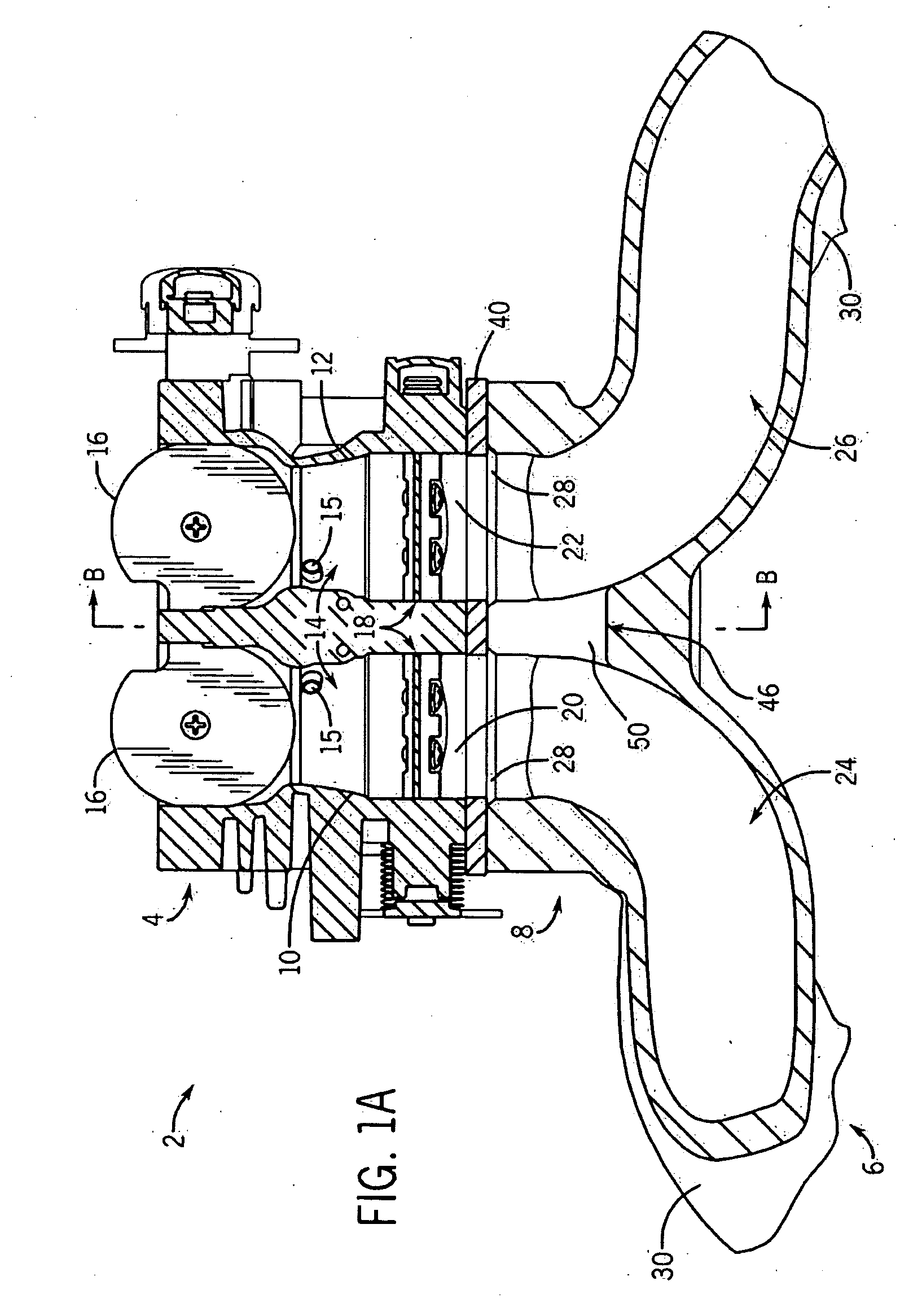
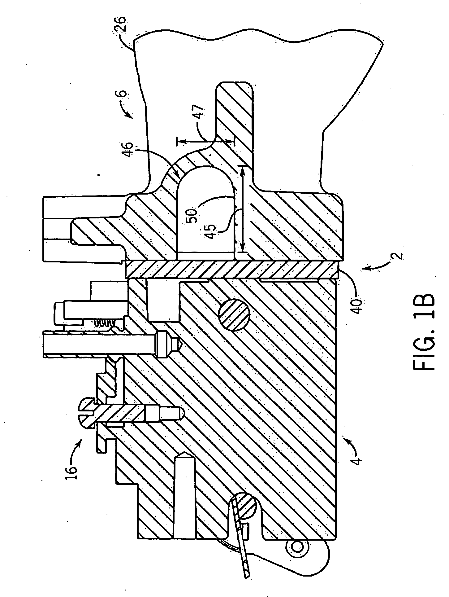
[0023]Referring to FIGS. 1A and 1B, first and second cross-sectional views are provided, in cutaway, of portions of an air intake assembly 2 of a horizontal crankshaft internal combustion engine, in accordance with a first embodiment of the present invention. The cross-sectional view of FIG. 1A in particular is a top cross-sectional view, that is, a view that would be obtained if one looked downward at a cross-section of the air intake assembly 2 (as oriented for normal operational circumstances) when an upper portion of that assembly was removed. As for the cross-sectional view of FIG. 1B, that view in particular is a side cross-sectional view of the air intake assembly 2 taken along a line B-B of FIG. 1A. As shown, the air intake assembly 2 in the present embodiment includes a carburetor 4 and an intake manifold 6, which includes a communication port 8 configured for interfacing an output port of the carburetor.

[0024]With respect to the carburetor 4 in particular, it is a two-barr...


PUM


Abstract

A manifold, such as an intake manifold or a fuel injection manifold, for use in an internal combustion engine, as well as a method of operating such an engine, are disclosed. In at least one embodiment, the manifold includes an input end capable of being coupled at least indirectly to an air input device, first and second intake tubes linking the input end to first and second exit ports, respectively, and a first communication channel linking the first and second intake tubes. The communication channel has a first width that is substantially less than a second width of at least one of the first and second intake tubes, and the communication channel links upper portions of the first and second intake tubes, while lower portions of the intake tubes remain separated by a wall.

Description

CROSS-REFERENCE TO RELATED APPLICATIONS[0001]This application claims the benefit of U.S. provisional patent application No. 60 / 949,372 filed on Jul. 12, 2007 and entitled “Manifold Communication Channel”, which is hereby incorporated by reference herein.STATEMENT REGARDING FEDERALLY SPONSORED RESEARCH OR DEVELOPMENT[0002]Not applicableFIELD OF THE INVENTION[0003]The present invention relates to internal combustion engines and, more particularly, relates to air intake components such as intake manifolds that are employed in internal combustion engines.BACKGROUND OF THE INVENTION[0004]Internal combustion engines are used in a wide variety of applications including, for example, automobiles, boats, aircraft, lawnmowers, tractors, snow blowers, and power machinery. Many such internal combustion engines employ a carburetor to provide an appropriate fuel / air mixture (often referred to as “charge”) to the combustion chamber(s) of a cylinder block. Further, in many such engines that employ ...

Claims


Application Information

Patent Timeline
Patent Type & Authority Applications(United States)
IPC IPC(8): F02M35/10
CPCF02D9/1095F02M11/02F02M35/116F02M35/10124F02M35/10196F02M35/10032
Inventor SHERIDAN, BRIAN MICHAEL HYNESPROPSON, JOEL A.ATKINSON, WILLIAM HARVEY
Owner KOHLER CO
Why Eureka
Try Eureka