
Ultrasonic treatment chamber having electrode properties

a technology of ultrasonic treatment chamber and electrode, which is applied in the direction of liquid fuel feeders, machines/engines, mechanical vibration separation, etc., can solve the problems of increasing the time and cost of the removal of unbound components from aqueous effluent, prolonging the adsorption process, and increasing the pressure drop across the reactor

Inactive Publication Date: 2009-01-15
KIMBERLY-CLARK WORLDWIDE INC
View PDF99 Cites 40 Cited by
  • Summary
  • Abstract
  • Description
  • Claims
  • Application Information

AI Technical Summary

Benefits of technology

[0008]In one aspect, a treatment chamber for treating a liquid generally comprises an elongate housing having longitudinally opposite ends and an interior space. The housing is generally closed at least one of its longitudinal ends and has at least one inlet port for receiving liquid into the interior space of the housing and at least one outlet port through which liquid is exhausted from the housing following ultrasonic t

Problems solved by technology

One problem with processing aqueous effluent through a column such as that of a conventional plug flow reactor, is that many of the components to be adsorbed (e.g., dyes and reactants) must travel through a hydrodynamic boundary layer surrounding the bead or particle.
This boundary layer is a source of resistance for the components, which prolongs the adsorption process and increases time and costs of the removal of unbound components from aqueous effluents.
Additionally, there is increased pressure drop across the reactor, and as such, larger plug flow reactor geometries and processing equipment are required.
Historically, however, ozone decontamination has not been used for highly concentrated contaminants because it is difficult to get enough ozone into the water and the capital and energy costs are too high.
In addition, these high concentration waste fluids are very sudsy.
Using a gas, such as ozone, to oxidize the contaminants introduces the problem of stable suds formation pump and consequent cavitation.

Method used


Image

  • Ultrasonic treatment chamber having electrode properties
  • Ultrasonic treatment chamber having electrode properties
  • Ultrasonic treatment chamber having electrode properties

Examples


Embodiment Construction

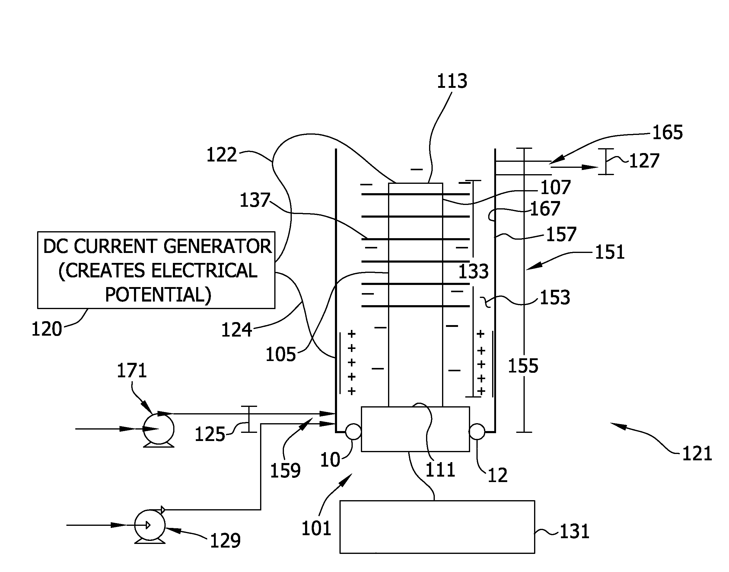
[0027]With particular reference now to FIG. 1, in one embodiment a system for treating a liquid generally comprises a treatment chamber, generally indicated at 121, that is operable to ultrasonically treat and electrolyze a liquid. It should be understood that when the treatment chamber of the present disclosure is used in some applications, the liquid will not be electrolyzed. For example, when the treatment chamber is used for mixing components together, electrolysis is not needed or desired. However, having electrode-like properties, the treatment chamber can improve the mixing of components and other chemical reactions. Specifically, it has been found that many reactions not easily or even impossible to make chemically, can easily and conveniently be produced electrochemically (e.g., producing reactive species such as superoxide ions, hydroxyl radicals, peroxides, carbon dioxide anion radicals, hydrogen atoms, metal hydrides, halogens, and the like). Furthermore, processing liqu...


PUM


Abstract

A liquid treatment chamber having an elongate housing through which liquid flows longitudinally from an inlet port to an outlet port thereof is disclosed. An elongate ultrasonic waveguide assembly extends within the housing and is operable at a predetermined ultrasonic frequency and a predetermined electrode potential to ultrasonically energize and electrolyze liquid within the housing. An elongate ultrasonic horn of the waveguide assembly is disposed at least in part intermediate the inlet and outlet ports, and has a plurality of discrete agitating members in contact with and extending transversely outward from the horn intermediate the inlet and outlet ports in longitudinally spaced relationship with each other. The horn and agitating members are constructed and arranged for dynamic motion of the agitating members relative to the horn at the predetermined frequency and to operate in an ultrasonic cavitation mode of the agitating members corresponding to the predetermined frequency and the liquid being treated in the chamber.

Description

FIELD OF DISCLOSURE[0001]The present disclosure relates generally to systems for ultrasonically treating and electrolyzing a liquid, such as an aqueous effluent, more particularly for ultrasonically treating and electrolyzing a flowing liquid, and even more particularly to a system including a treatment chamber for ultrasonically and electrolyzing an aqueous effluent to treat one or more components from the aqueous effluent.BACKGROUND OF DISCLOSURE[0002]A substantial number of liquids must be treated to meet government laws for release into the environment. For example, many aqueous streams typically contain one or more impurities, such as suspended solids, dissolved organic matter, microorganisms, dissolved mineral matter and the like. Another example is in textile dyeing and printing processes. Specifically, in nearly all textile dyeing and printing processes, some fraction of the applied colorant will not bind to the substrate. These unbound dyes and reactants are typically remov...

Claims


Application Information

Patent Timeline
IPC IPC(8): B06B1/02
CPCC02F1/36C02F2303/04C02F1/4676C02F1/4672
Inventor JANSSEN, ROBERT ALLENAHLES, JOHN GLENEHLERT, THOMAS DAVIDMACDONALD, JOHN GAVINMCCRAW, JR., EARL C.MCNICHOLS, PATRICK SEANRASMUSSEN, PAUL WARRENROFFERS, STEVE
Owner KIMBERLY-CLARK WORLDWIDE INC
Learn More