Paint spraying apparatus

a spraying apparatus and paint technology, applied in the direction of spray nozzles, liquid spraying apparatus, packaging, etc., can solve the problems of affecting the safety of workers, so as to reduce the risk of lung cancer, simple construction, and convenient operation.

Inactive Publication Date: 2009-01-15
HINES STEPHEN P
View PDF3 Cites 1 Cited by
  • Summary
  • Abstract
  • Description
  • Claims
  • Application Information

AI Technical Summary

Benefits of technology

[0011]It is an object of the present invention to provide a simple, easy-to-use and inexpensive apparatus for effectively capturing overspray during paint spraying operations. More particularly, it is an object of the invention to provide a novel exhaust system for capturing overspray that comprises a vacuum hose that is directly interconnected with the paint spray device and is strategically positioned in close proximity to the spray nozzle of the paint spray device.
[0014]Another object of the invention is to provide an apparatus of the character described that can be used with a conventional aerosol paint spray can and in which the vacuum hose of the conventional household-type vacuum cleaner is directly connected to a special aerosol can-gripping device that can be interconnected with the top of the aerosol spray and can conveniently be used to operate the valve system.
[0015]Still another object of this invention to provide an overspray capture apparatus that is of a simple construction, requires minimum maintenance and is inexpensive to manufacture and install.

Problems solved by technology

Research has shown that higher risks of lung cancer, leukemia, liver cancer, stomach cancer and bladder cancer are related to long-term paint exposure.
Accordingly, a major health hazard concern of the spray coating process is ‘overspray’, that is, the small aerosols that do not impact the work piece.
If overspray is not contained, it can drift and land on nearby materials or workers.
Additionally, bounce-back particles, that is, the small aerosols that bounce off or entirely miss the surface after leaving the spray gun, if not contained, can also drift and land on nearby materials or workers.
Studies have shown that the single exhaust fan is quite ineffective in controlling the paint overspray.
However, experience has shown that in the typical workplace the respirators and spray booths are often improperly maintained, and, accordingly, frequently offer little meaningful protection to the worker.
Similarly, users of aerosol paint spray cans seldom use respirators or other types of protective devices.

Method used


Image

  • Paint spraying apparatus
  • Paint spraying apparatus
  • Paint spraying apparatus

Examples


Embodiment Construction

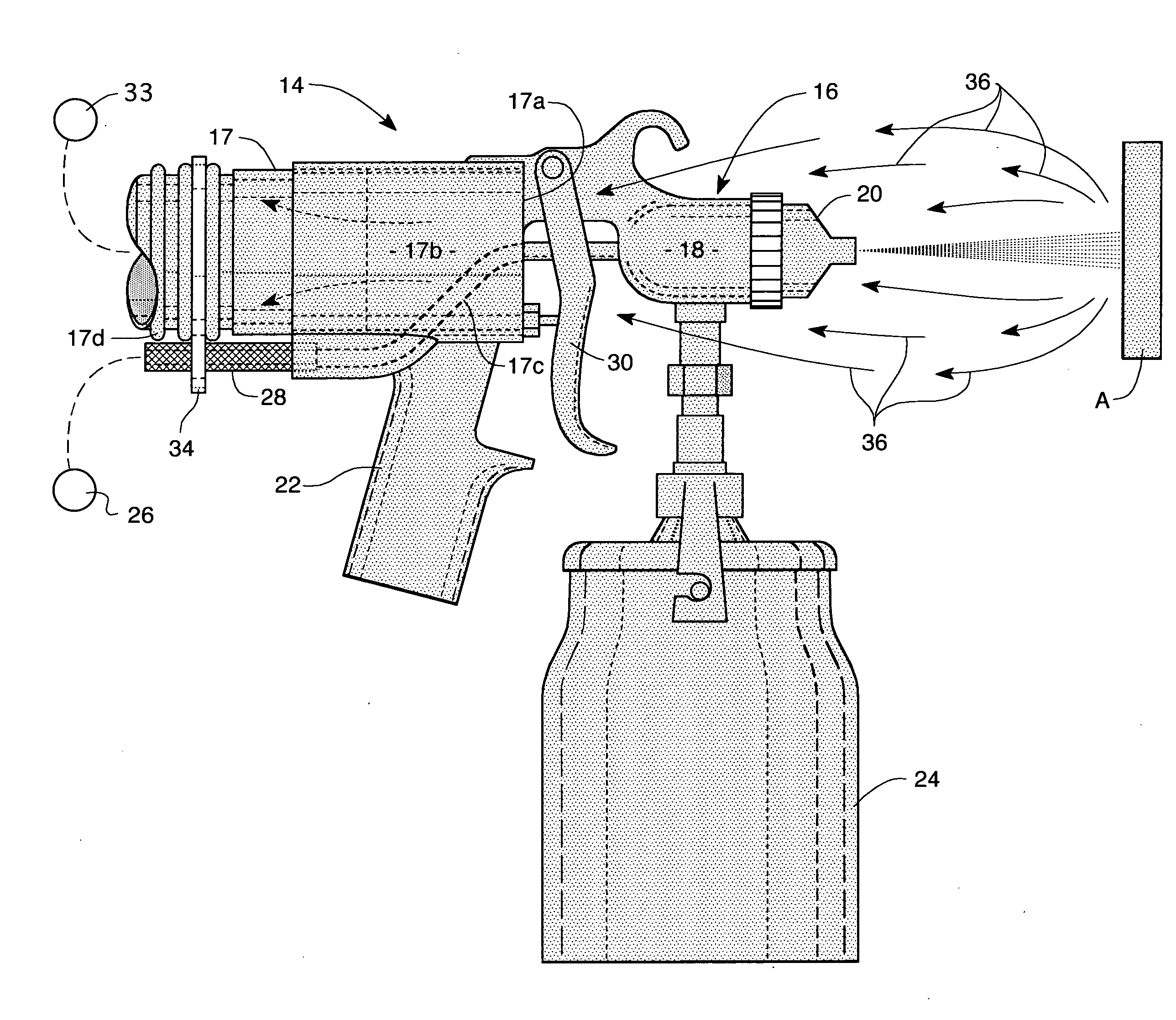
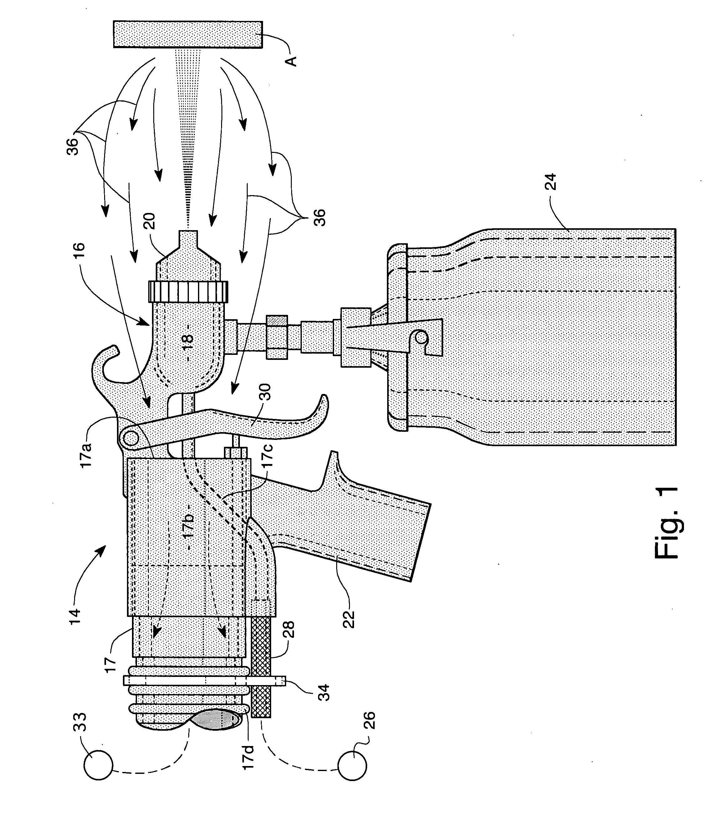
[0020]Referring to the drawings and particularly FIG. 1, one form of the overspray and bounce-back capture apparatus of the present invention is there shown in generally designated by the numeral 14. The apparatus here comprises a conventional, readily commercially available type paint spray gun assembly 16 and a vacuum hose 17 that is operably interconnected with the spray gun assembly in the manner shown in FIG. 1. Spray gun assembly 16, which is of conventional construction, comprises a central atomizing chamber 18 having a spray nozzle 20 affixed to one end thereof and a handle portion 22 affixed to the opposite end thereof. In a manner indicated in FIG. 1 of the drawings, a conventional pressurized paint container 24 is operably interconnected with atomizing chamber 18. A source of compressed air 26 is interconnected with atomizing chamber 18 by means of an elongated flexible conduit 28. Interconnected with handle portion 22 is a finger-operated trigger mechanism 30 that contro...


PUM


Abstract

An exhaust system for capturing overspray from conventional paint spray guns and aerosol paint spray cans that including a vacuum hose that is directly interconnected with the paint spray device being used and is strategically positioned in close proximity to the spray nozzle of the paint spray device. In one form of the invention a conventional household-type vacuum cleaner has the vacuum source.

Description

BACKGROUND OF THE INVENTION[0001]1. Field of the Invention[0002]The present invention relates generally to paint spraying apparatus. More particularly, the invention concerns a novel paint spray apparatus in which a conventional paint spraying device is interconnected with a vacuum conduit for capturing bounce-back overspray.[0003]2. Discussion of the Prior Art[0004]Paint spraying is widely used in various industries for applying a uniform coating of paint to a work piece. Such a technique is particularly widely used in the automotive industry for painting vehicles. Typically paint spraying is accomplished using a basic spray painting system that consists of a conventional compressed air spray gun, a pressurized paint container, a compressed air system, and conduits connecting these components. Applying the coating material to the work piece is fairly straightforward and conventional, or atomized spray systems typically use air at high pressure (40-70 pounds per square inch) to atom...

Claims


Application Information

Patent Timeline
Patent Type & Authority Applications(United States)
IPC IPC(8): B05B1/28
CPCB05B7/2405B65D83/202B05B15/0406B05B7/2467B05B14/00
Inventor HINES, STEPHEN P.
Owner HINES STEPHEN P
Why Eureka
Try Eureka