Plastic aerosol valve and method of assembly, mounting and retention

a technology of aerosol valves and aerosol gas, which is applied in the direction of single-unit apparatuses, transportation and packaging, and other domestic objects, can solve the problems of non-removable retention, general failure to achieve commercial success, and non-removable retention, and achieves the effect of preventing the loss of propellent gas and easy recycling

Inactive Publication Date: 2009-01-15
PRECISION VALVE CORP
View PDF34 Cites 167 Cited by
  • Summary
  • Abstract
  • Description
  • Claims
  • Application Information

AI Technical Summary

Benefits of technology

[0009]It will be appreciated that the assembled aerosol valve will generally be sold to fillers with the upper portion of the locking ring in its upper, non-telescoped position. After the PET bottle is filled by the filler with the product to be dispensed, the filler will attach the aerosol valve assembly by pushing it down onto the PET bottle in the manner as referenced above, and will then push the upper portion of the locking ring down to telescope over the lower portion. The speed and ease at which these push-down operations can be carried out is a decided advantage of the present invention.
[0010]It is therefore apparent that the aerosol valve of the present invention can be assembled by simple insertion of parts, snap action features of the plastic parts, and locking and retaining features of the plastic parts. The necessity in the prior art of machine tools to clinch and crimp metal mounting cups onto valve housings and onto product containers is thereby avoided.
[0011]The present invention also can be free of metal parts, and is easily recycled. No metal spring is required in the present invention to maintain the valve closed in the absence of actuation, with the flex of the stem gasket acting against a groove in the valve stem to close the aerosol valve after actuation. If desired, however, metal (or plastic) return springs may be utilized.
[0012]The present invention further may include a check valve movable in the valve stem to hinder loss of propellent gas if the plastic valve and bottle are actuated in the inverted position.

Problems solved by technology

These attempts have generally not been successful commercially, due to concerns about reliable and non-removable retention and sealing of the mounting cup, potential assembly issues, etc.

Method used


Image

  • Plastic aerosol valve and method of assembly, mounting and retention
  • Plastic aerosol valve and method of assembly, mounting and retention
  • Plastic aerosol valve and method of assembly, mounting and retention

Examples


Embodiment Construction

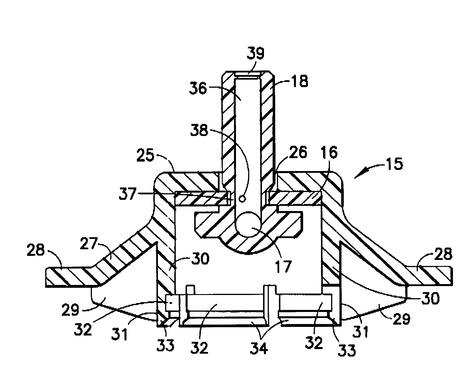
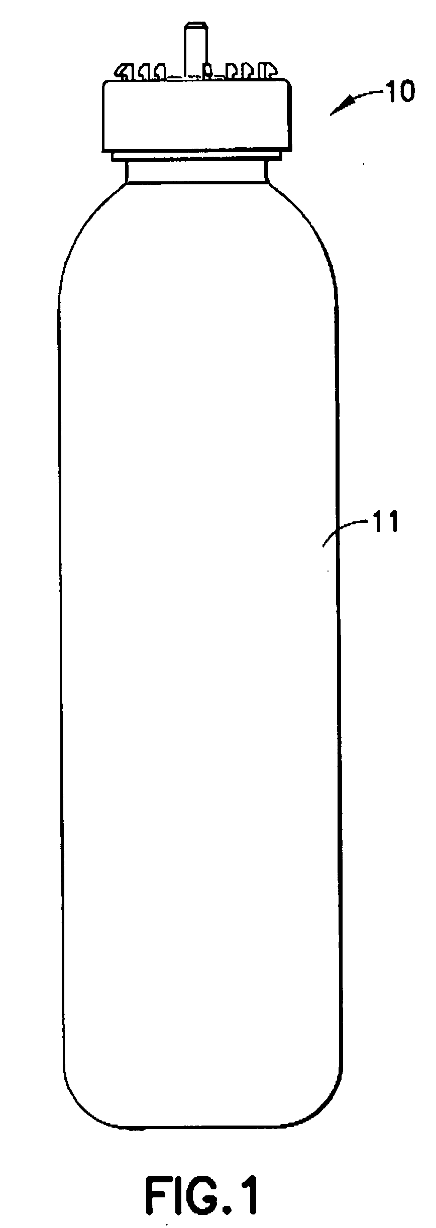
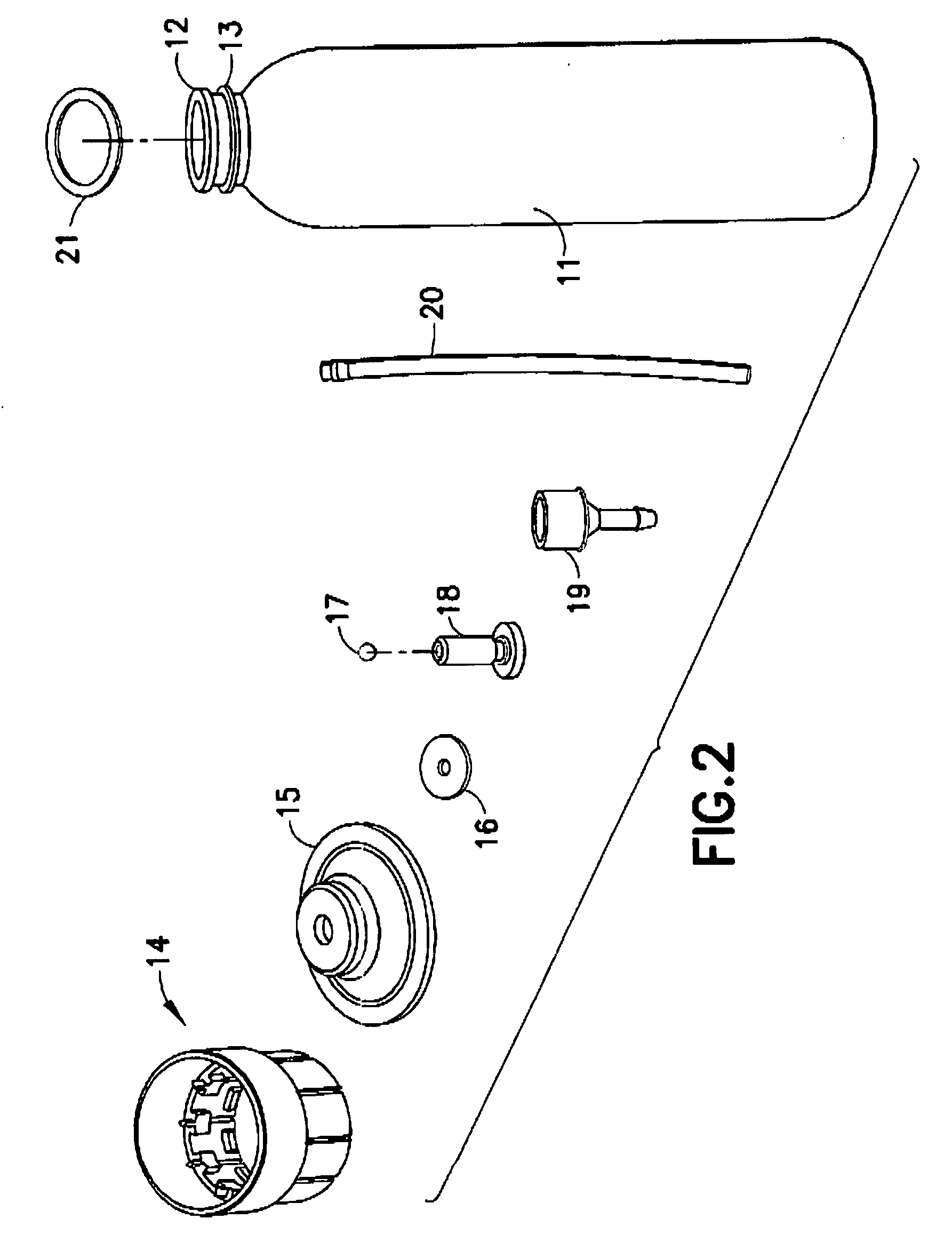
[0031]Referring to FIG. 1, the assembled plastic aerosol valve 10 of the present invention is shown mounted to the top of plastic PET bottle 11. FIG. 2 illustrates bottle 11 having spaced circumferential flanges 12 and 13 extending outwardly on the neck of the bottle. The components of plastic aerosol valve 10 are shown in FIG. 2, comprising plastic locking ring 14, plastic mounting cup 15, rubber (or TPE) stem gasket 16, ball check valve 17, plastic valve stem 18, plastic valve housing 19, plastic dip tube 20, and rubber (or TPE) mounting cup sealing gasket 21. The plastic of the locking ring 14, mounting cup 15, valve stem 18, valve housing 19 and dip tube 20 may also be PET. The mounting cup 15, valve stem 18, stem gasket 16, valve housing 19 and dip tube 20 of the present invention broadly perform the usual well-known functions of such elements in an aerosol valve. The valve stem, stem gasket and valve housing are captured within the mounting cup and the dip tube is attached to ...


PUM

PropertyMeasurementUnit
diameteraaaaaaaaaa
outer diameteraaaaaaaaaa
inner circumferenceaaaaaaaaaa

Abstract

A plastic aerosol valve with a plastic valve stem, plastic housing, plastic mounting cup, and plastic locking ring. The plastic valve is assembled into the mounting cup. The plastic housing is assembled into the plastic mounting cup by snap fittings. The plastic mounting cup has a peripheral portion that snap fits up into the plastic locking ring. The plastic locking ring has frangibly-connected upper and lower portions. The lower portion snap fits with the top of a plastic product bottle to mount the aerosol valve assembly on the bottle. The upper ring portion thereafter is telescoped downwardly over the lower ring portion to lock and retain the aerosol valve assembly on the pressurized bottle. The plastic mounting cup can be molded separately, or integrally with the plastic locking ring. A check valve may be contained in the valve stem.

Description

FIELD OF THE INVENTION[0001]The present invention relates to aerosol valves. More particularly, this invention relates to a new design of plastic aerosol valve and the method of assembling the valve, mounting the valve onto a preferably plastic container, and retaining the valve on the container.BACKGROUND OF THE INVENTION[0002]The most common and long existing aerosol valve design generally comprises a plastic valve stem mounted within a plastic valve housing which in turn is mounted into a metal mounting cup. The metal mounting cup is formed with a central pedestal portion having a central opening for the plastic valve stem. The metal pedestal portion is clinched by machine tooling onto the plastic valve housing to retain the housing in the mounting cup. The metal mounting cup also has an outer portion with a circumferential channel and an outer skirt. The channel is fitted onto the bead about the top opening of a generally metal aerosol product container for holding propellant an...

Claims


Application Information

Patent Timeline
Patent Type & Authority Applications(United States)
IPC IPC(8): F16K51/00B21K1/20
CPCB05B11/3049B65D83/38Y10T29/49412B65D83/48B65D83/56B65D83/42B65D83/565B05B11/1049
Inventor HYGEMA, TERRY L.BRACE, GEOFFFORE, JOHN B.FLYNN, RANDY J.
Owner PRECISION VALVE CORP
Why Eureka
Try Eureka