
Method for suppressing variation in speed of actuator

a technology of actuator and speed, applied in the direction of electric programme control, program control, instruments, etc., can solve the problems of affecting the rotational speed of the actuator output shaft, the angle transmission error of the wave gear drive, and the error of the actuator

Inactive Publication Date: 2009-01-15
HARMONIC DRIVE SYST IND CO LTD
View PDF7 Cites 10 Cited by
  • Summary
  • Abstract
  • Description
  • Claims
  • Application Information

AI Technical Summary

Benefits of technology

[0021]In the speed feedback values used for feedback control of the actuator in the present invention, a speed component caused by the angle transmission error of the wave gear drive is added to the speed computed from the detected position of the motor rotating shaft. Feedback is therefore used to control the speed, whereby variation in the rotational speed of the actuator output shaft caused by angle transmission error of the wave gear drive can be effectively suppressed.

Problems solved by technology

Angle transmission error occurs in the wave gear drive in this instance.
Error occurs between the target position and the actual position of the actuator output shaft (the output shaft of the wave gear drive) due to this angle transmission error.
However, variations in the rotational speed of the actuator output shaft occur due to the effects of an error component in the wave gear drive in actuators provided with a wave gear drive.

Method used


Image

  • Method for suppressing variation in speed of actuator
  • Method for suppressing variation in speed of actuator
  • Method for suppressing variation in speed of actuator

Examples


Embodiment Construction

[0046]An example of a drive controller of an actuator in which the method of the present invention is applied will be described below with reference to the drawings.

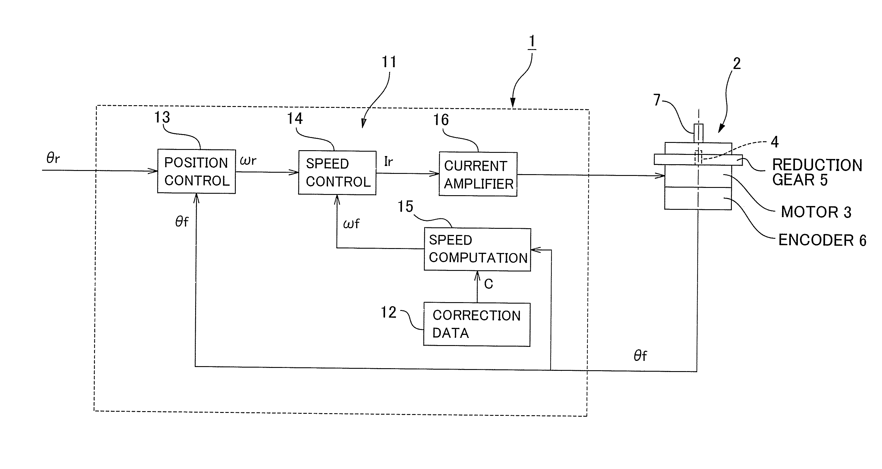
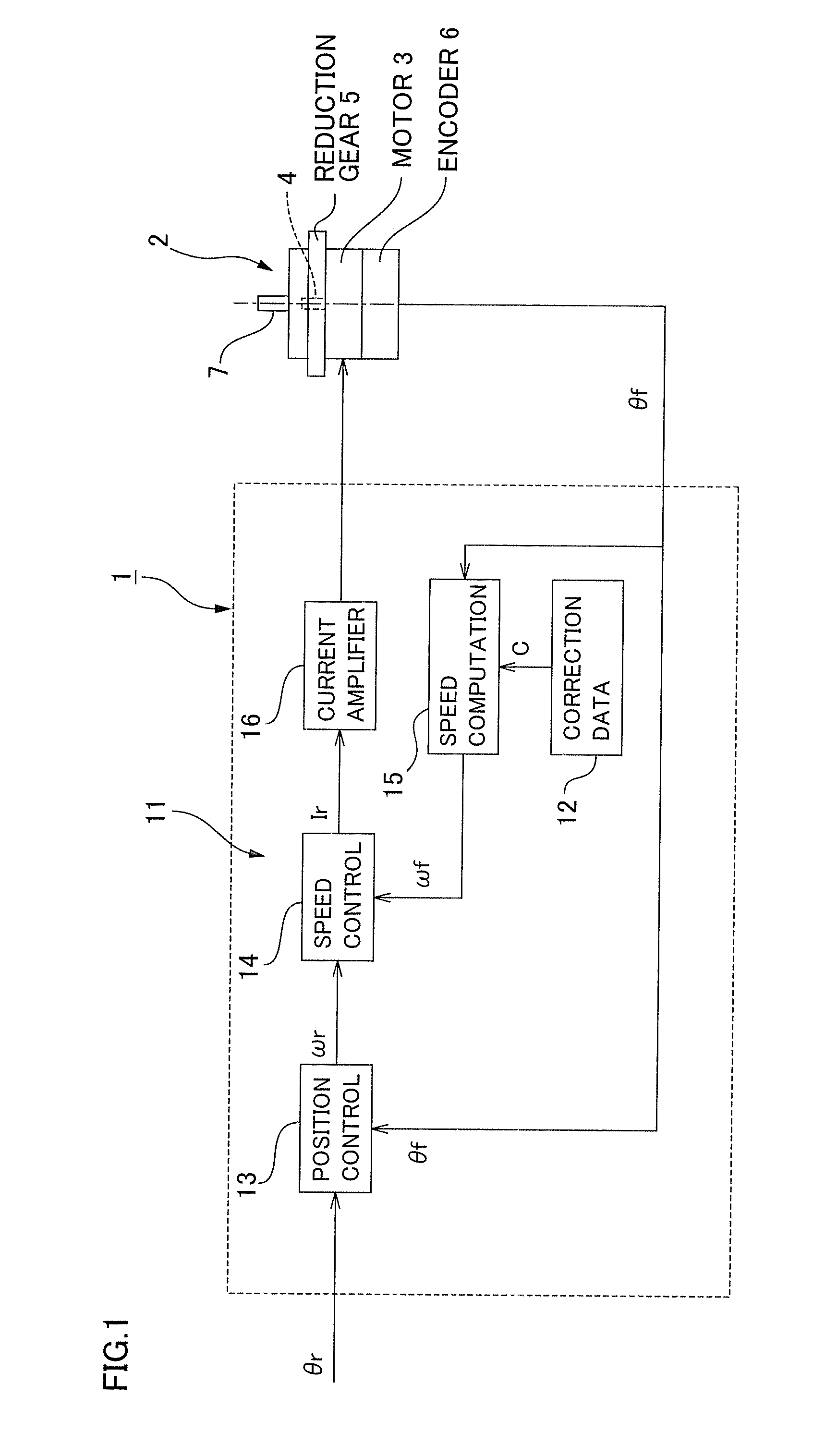
[0047]FIG. 1 is a schematic structural diagram that shows a drive controller of an actuator of the present example. An actuator 2 of the present example that is driven by this drive controller 1 comprises a motor 3, a wave gear drive 5 linked to a motor rotating shaft 4, and a position detector 6 that is capable of detecting the rotational position of the motor rotating shaft 4. The output shaft, i.e., an actuator output shaft 7, of the wave gear drive 5 is linked to a load (not shown). The position detector 6 is a rotary encoder, potentiometer, or another position detector that is capable of detecting absolute position.

[0048]The drive controller 1 for controlling the driving of the actuator 2 comprises a feedback-control part 11 for performing feedback control so that the actuator 2 assumes a target position designated ...


PUM


Abstract

The drive controller of an actuator previously measures positioning error of an actuator output shaft caused by the angle transmission error of a wave gear drive and stores it as correction data. In a feedback control loop, a speed feedback value ωf is computed using the detected position feedback value θf, after corrected by the correction data, of the actuator output shaft, and a current command Ir is computed using it, thus performing drive control on a motor. Since a speed component caused by the angle transmission error of the wave gear drive has been added to the rotational speed of a motor with regard to the speed feedback value ωf, a variation in rotational speed of the actuator output shaft caused by the angle transmission error of a wave gear drive can be suppressed effectively.

Description

TECHNICAL FIELD[0001]The present invention relates to a method for suppressing variation in the speed of an actuator, in which variation in the rotational speed of an actuator output shaft caused by angle transmission error of a wave gear drive is suppressed in an actuator provided with the wave gear drive. The present invention also relates to a drive controller of an actuator in which this method for suppressing variation in speed is employed.BACKGROUND ART[0002]Well-known actuators include configurations in which the rate of output rotation of a motor is reduced by a wave gear drive, and a load-side member is held in a target position. The wave gear drive is provided with an annular, rigid internally-toothed gear, an annular, flexible externally-toothed gear, and a wave generator. In a typical wave gear drive, a state is created in which the flexible externally-toothed gear is bent into an elliptical shape by the wave generator, and the external tooth portions positioned on both ...

Claims


Application Information

Patent Timeline
Patent Type & Authority Applications(United States)
IPC IPC(8): G05B19/404H02P29/00G05D3/12
CPCG05B19/416G05B2219/41215H02P6/10
Inventor SASAKI, KOZOMIYASHITA, KUNIO
Owner HARMONIC DRIVE SYST IND CO LTD
Learn More