Radio frequency identification tagging

a radio frequency identification and tag technology, applied in the field of radio frequency identification (rfid) tagging, can solve the problems of limiting the size of any doorway or portal, limiting the ability of a rfid reader to successfully read the tag, etc., to achieve the effect of reducing the size, facilitating the use of tag objects, and wearing with more comfor

Active Publication Date: 2009-01-15
ZEBRA TECH CORP
View PDF1 Cites 45 Cited by
  • Summary
  • Abstract
  • Description
  • Claims
  • Application Information

AI Technical Summary

Benefits of technology

[0067]Due to its reduced size the RFID tag structure can be more easily used to tag objects, and when used to tag humans or animals it can be worn with more comfort.
[0068]Pursuant to a related aspect the inventors have researched how the wearing comfort of a RFID tag structure can be increased. He has found that the ground plane can be made from a flexible material, such as a metallic mesh or a foil.

Problems solved by technology

However, with currently permitted radio power levels under radio regulations in many jurisdictions the operating or reading range of standard tags is 70 cm or less, which limits the size of any doorway or portal.
Furthermore, the physical orientation of the tag can limit the ability of a RFID reader to successfully read the tag.

Method used


Image

  • Radio frequency identification tagging
  • Radio frequency identification tagging
  • Radio frequency identification tagging

Examples


Embodiment Construction

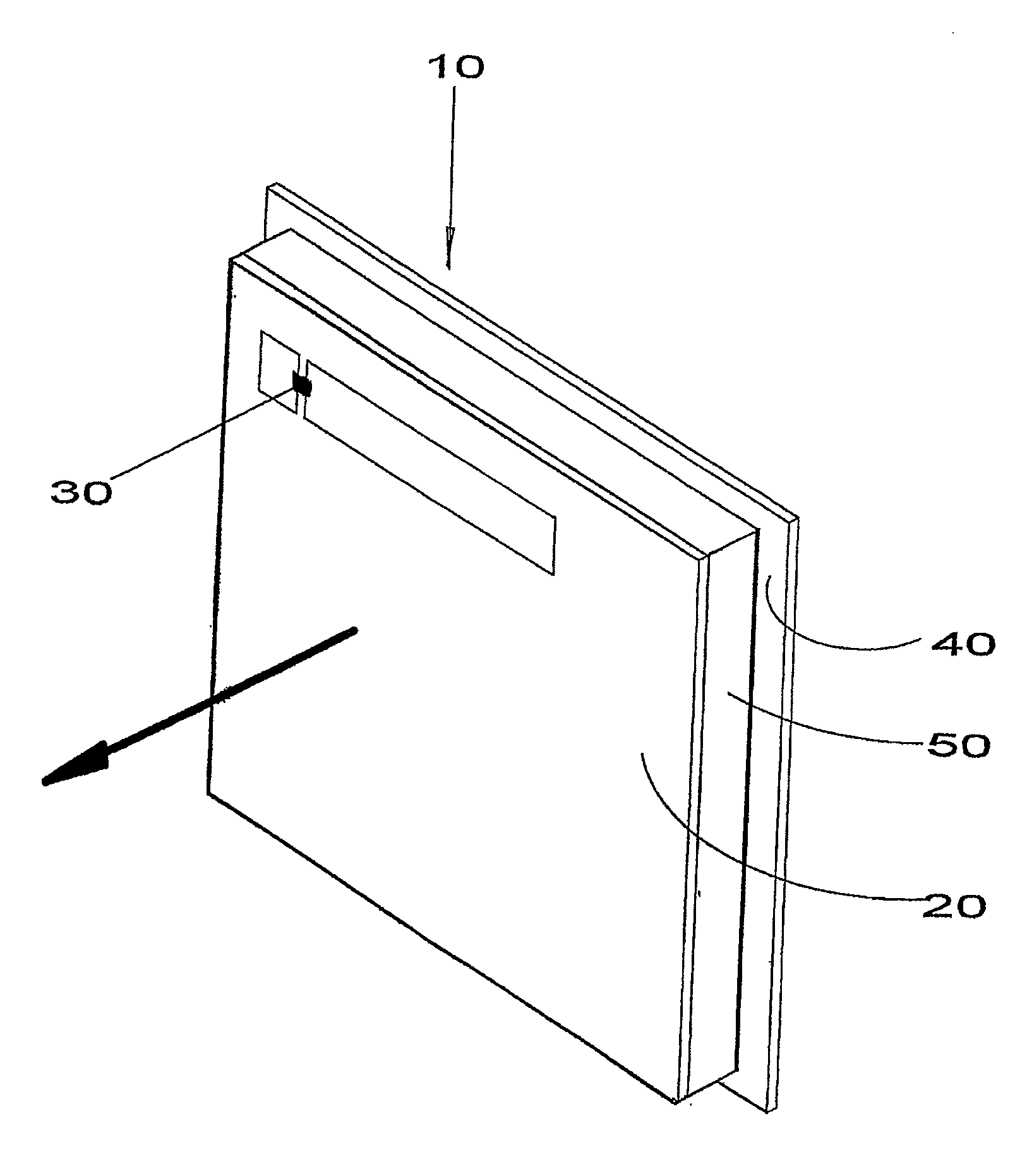
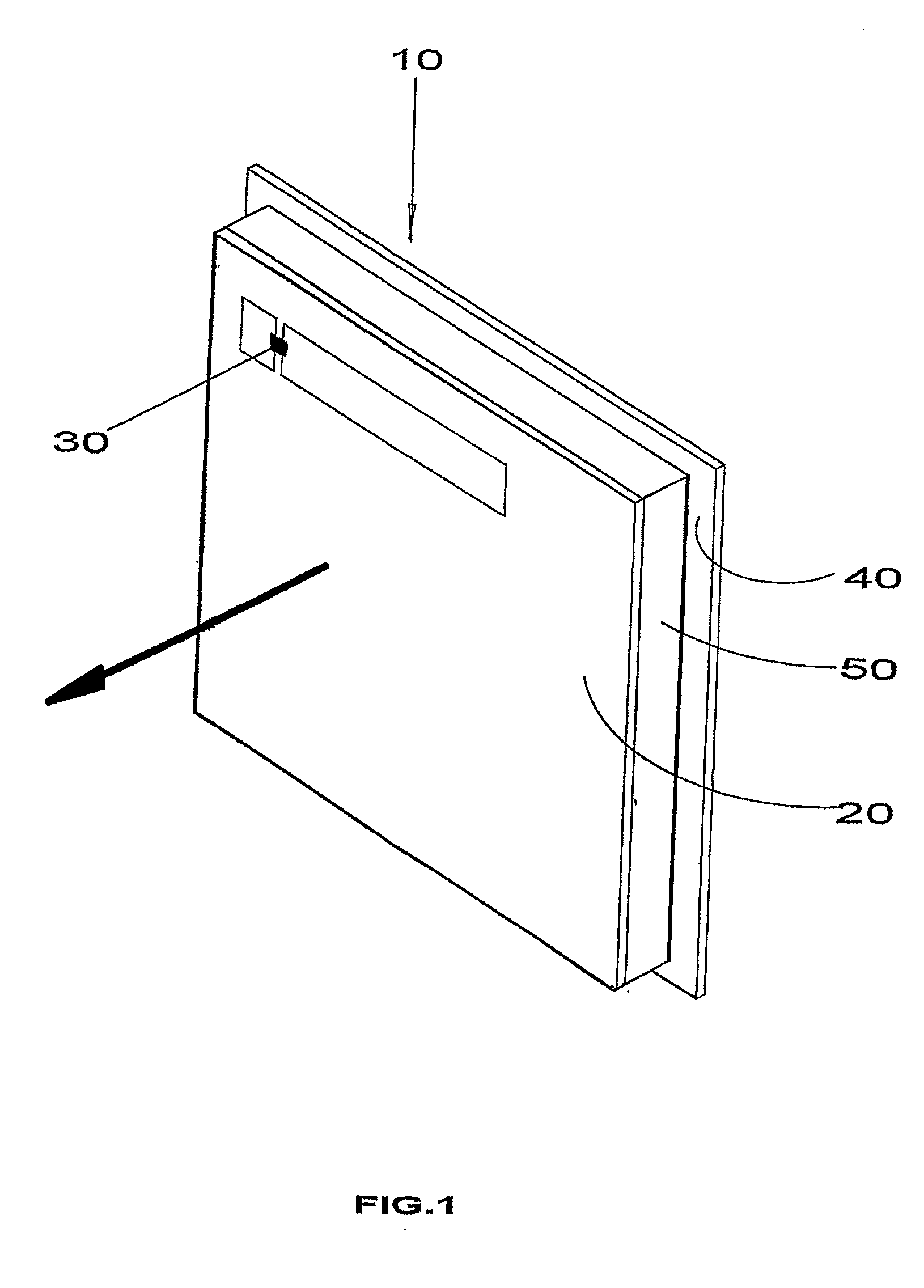
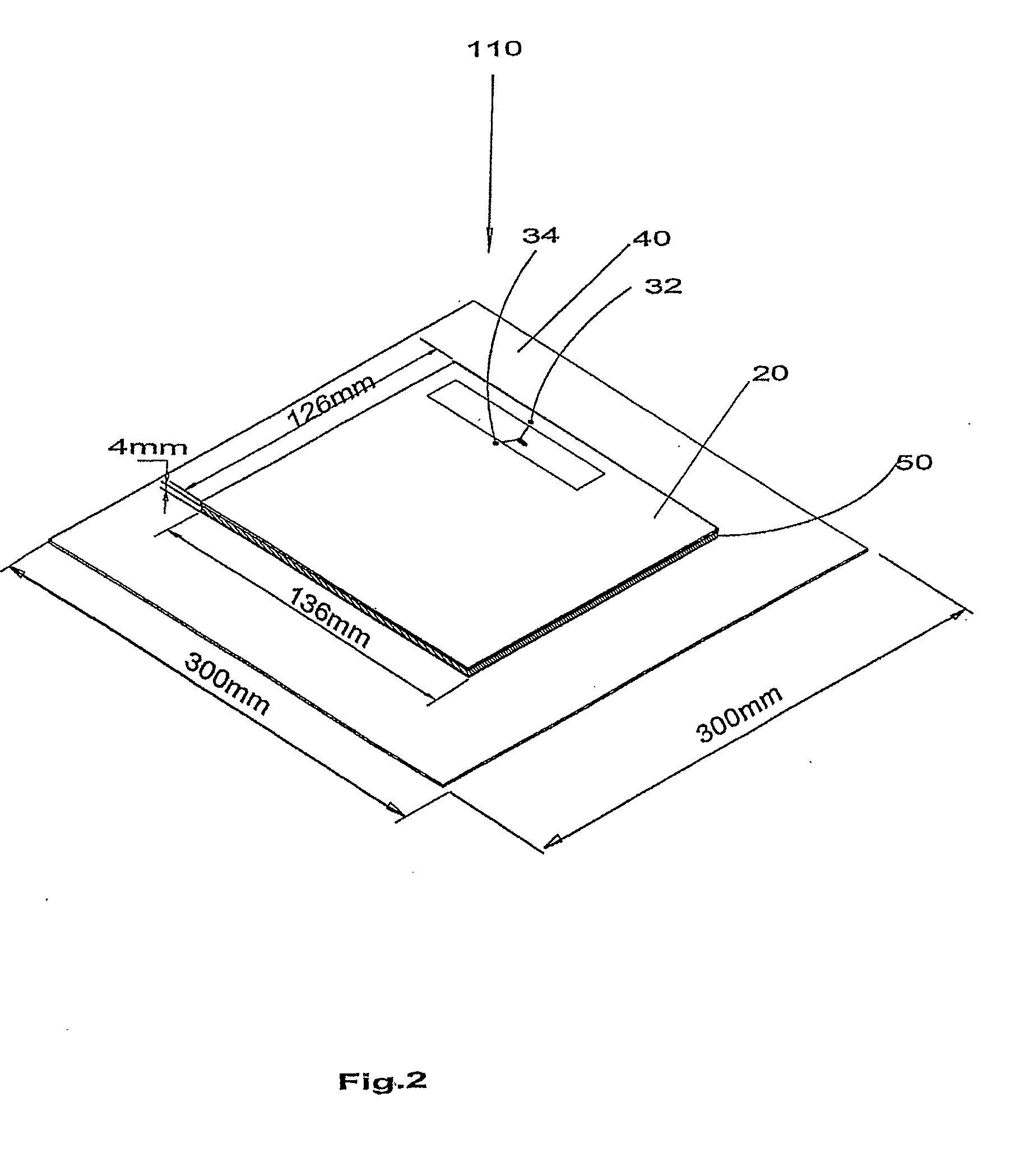
[0099]Referring now to FIG. 1, a first embodiment of a passive RFID tag antenna structure according to the present invention is shown. The RFID tag antenna structure 10 comprises a patch antenna 20 with a RFID tag integrated circuit 30. A ground plane 40 of metallic material is provided, which extends parallel to the patch antenna 20. The area spanned by the ground plane 40 is only slightly larger than the area spanned by the patch antenna 20. A dielectric 50 fills the space between the patch antenna 20 and the ground plane 40.

[0100]Whilst a relatively large absorbing body such as a bucket of water or a human body would absorb most of the RF power of the patch antenna without the ground plane when brought near the absorbing body, the ground plane 40 effectively shields the patch antenna 20 against absorbing bodies “behind” the ground plane 40, even if such absorbing bodies are much larger than the ground plane 40. Since the ground plane 40 is only slightly larger than the patch ante...


PUM


Abstract

A RFID tag or label comprises a RFID tag module (comprising an electronic identification circuit and a coupling means) and an antenna structure coupled to the coupling means. The RFID tag module is separate from, separable or arranged to be severable from, the antenna structure. The tag module can be placed in or on an object and the antenna structure in or on packaging material for use with the object. A patch antenna type RFID tag antenna structure has a ground plane spaced from the patch antenna so as to increase the range of the tag. The ground plane is not substantially larger than, and electrically insulated from, the patch antenna. The ground plane is flexible, so the RFID tag structure can be worn by a human, and can be incorporated into a piece of clothing. A RFID antenna structure for use with a tag reader is made flat and robust so that it can be mounted on the ground to be walked upon or driven over. A bi-directional YAGI type RFID tag antenna structure has director elements on two opposite sides so that the YAGI antenna radiates in two opposite directions. An object includes a gain increasing metallic structure for increasing the gain of a RFID tag when placed near the object so as to form a RFID tag antenna structure.

Description

CROSS-REFERENCE TO RELATED APPLICATIONS[0001]The present application is a continuation of U.S. application Ser. No. 10 / 527,736, filed Mar. 14, 2005, which is a National Phase entry of International Application No. PCT / GB2003 / 003939, filed Sep. 12, 2003, both of which are hereby incorporated herein in their entirety by reference.FIELD OF THE INVENTION[0002]The present invention relates to various aspects of radio frequency identification (RFID) tagging. The invention is particularly applicable to passive RFID tags, but can also be applied to powered RFID tags. In some aspects the invention relates to antenna structures for use in RFID tagging.BACKGROUND OF THE INVENTION[0003]Passive RFID tags which operate in the UHF band (860 to 920 MHz) are known in the art. Known RFID tags comprise a RFID integrated circuit or a RFID tag module which is attached to an antenna, which can be a dipole, folded dipole, loop or patch antenna. In many situations it is desirable to use passive RFID tags f...

Claims


Application Information

Patent Timeline
Patent Type & Authority Applications(United States)
IPC IPC(8): H04Q5/22G06K7/10G06K19/077H01Q1/22H01Q1/27H01Q19/28
CPCB65D2203/10G06K7/10178G06K7/10346G06K19/07749G06K19/07745G06K19/07786H01Q1/2225H01Q1/273H01Q19/28G06K19/0775G01V15/00G06K19/077
Inventor FOGG, MARTINTURNER, CHRISTOPHER GORDON GERVASE
Owner ZEBRA TECH CORP
Why Eureka
Try Eureka