Radar Apparatus and Mobile Object

Inactive Publication Date: 2009-01-15
MURATA MFG CO LTD
View PDF7 Cites 31 Cited by
  • Summary
  • Abstract
  • Description
  • Claims
  • Application Information

AI Technical Summary

Benefits of technology

[0062]Yet still furthermore, by providing collision avoiding means to the mobile

Problems solved by technology

However, in this method, even when the target is located in the upper front direction, and therefore, the target and the vehicle can pass each other, the radar apparatus determines that the target is an obstacle to the vehicle.
Thus, when going under an overpass or a traffic sign, the vehicle may receive an incorrect warning or an incorrect brake signal.
However, it is difficult to detect the direction (the azimuth direction) highly accurately.
As described above, since the two-dimensional moving velocity is computed using the computed low-accuracy azimuth direction, the estimated computed distance of closest approach includes an error to some extent.
If, as described in Patent Document 1, tracking is performed using an image output from a radar apparatus, such an erro

Method used


Image

  • Radar Apparatus and Mobile Object
  • Radar Apparatus and Mobile Object
  • Radar Apparatus and Mobile Object

Examples


first embodiment

[0088]A radar apparatus according to a first embodiment of the present invention is described with reference to the accompanying drawings. In this embodiment, a radar apparatus that employs an FMCW method using a transmission signal frequency-modulated in a triangular waveform is described as an example.

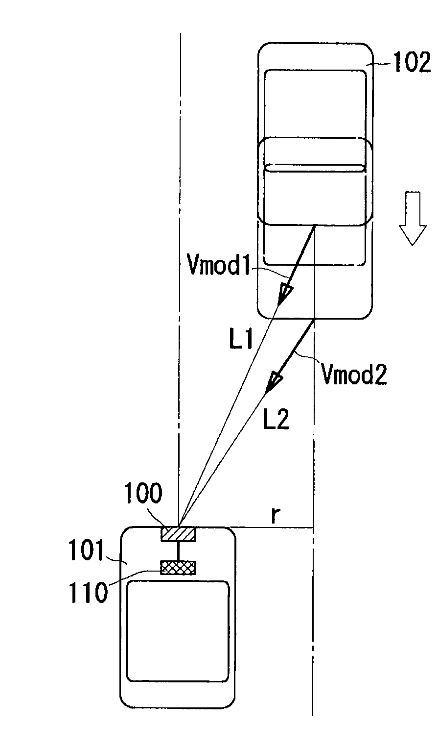
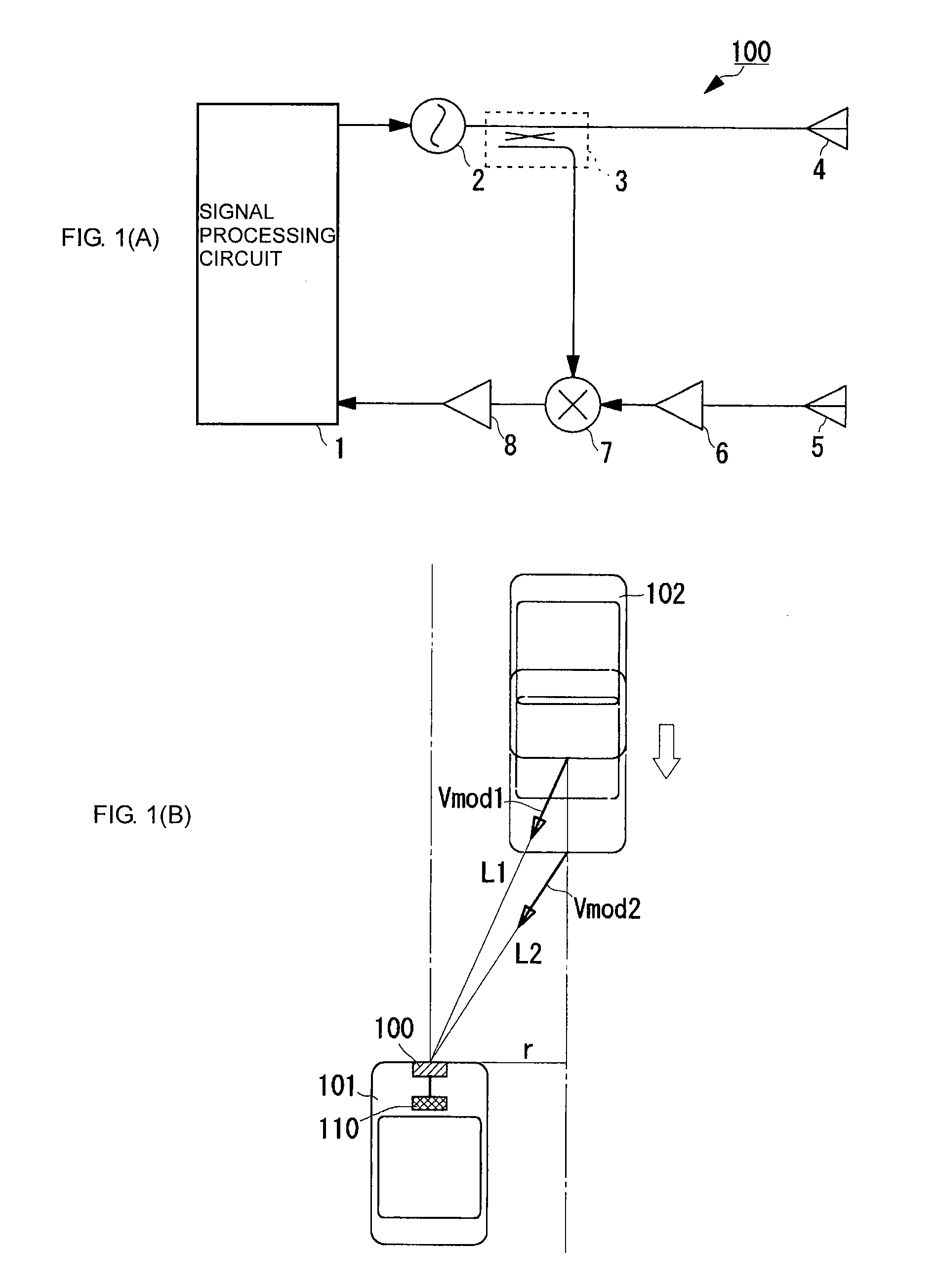
[0089]FIG. 1(A) is a block diagram of a main configuration of the radar apparatus according to the first embodiment. FIG. 1(B) illustrates a concept of a method for computing a distance of closest approach of an oncoming vehicle 102 to a vehicle 101 including a radar apparatus 100 mounted therein. Note that, in FIG. 1(B), the vehicle 101 is stationary. However, FIG. 1(B) illustrates a simplified situation for ease of description. In this example, the oncoming vehicle 102 is a detection object, and the vehicle 101 and the oncoming vehicle 102 are located in the same horizontal plane (i.e., the height of the oncoming vehicle 102 relative to the vehicle 101 is 0). Even when the vehicle ...

second embodiment

[0111]A radar apparatus according to a second embodiment is described next. According to the present embodiment, the radar apparatus has a configuration the same as that of the first embodiment. For example, the radar apparatus transmits pulses of electromagnetic waves or light and measures a distance on the basis of a time when the pulses reflected by an object is returned to the radar apparatus.

[0112]Such a radar apparatus cannot compute the above-described radar-apparatus-direction relative velocity Vmod. However, the radar apparatus can compute the distance L. In this case, for example, a predetermined short time interval Δt is set. By using a distance L11 at a beginning time point of the short time interval Δt and a distance L12 at an end time point of the short time interval Δt, the radar-apparatus-direction relative velocity Vmod1 can be computed using the following equation (13):

V mod1=(L11−L12) / Δt  (13)

[0113]In such a manner, by computing the radar-apparatus-direction relat...

third embodiment

[0114]A radar apparatus according to a third embodiment is described next. According to the present embodiment, the radar apparatus has a configuration in which the reception antenna 5 can perform a scanning operation in a predetermined direction of the detection area. The other configurations are similar to those of the radar apparatus of the first embodiment.

[0115]The reception antenna 5 includes a plurality of antennas along an azimuth direction (a horizontal direction in this case). The reception antenna 5 further includes a switch for sequentially switching the antennas. Alternatively, the reception antenna 5 includes a mechanism for scanning one antenna in the azimuth direction.

[0116]In such a configuration, detection signals sequentially input to the signal processing circuit 1 are time-series signals obtained from different azimuth directions. The signal processing circuit 1 sequentially acquires a detection signal for one scan cycle and stores the acquired detection signal ...


PUM


Abstract

A signal processing circuit detects, at a plurality of different timing points, a first and a second distance of an oncoming vehicle approaching a vehicle including the radar apparatus and detects a first and a second component of a relative velocity of the vehicle in the radar-apparatus direction. A distance of closest approach of the oncoming vehicle to the vehicle appears when the vehicle and the oncoming vehicle pass each other side by side. The signal processing circuit computes the distance of closest approach on the basis of a formula indicating that a relative velocity given by the first distance, the distance of closest approach, and the first component of a relative velocity in the radar-apparatus direction is equal to a relative velocity given by the second distance, the distance of closest approach, and the second component of a relative velocity in the radar-apparatus direction.

Description

CROSS REFERENCE TO RELATED APPLICATIONS[0001]The present application is a continuation of International Application No. PCT / JP2007 / 055068, filed Mar. 14, 2007, which claims priority to Japanese Patent Application No. JP2006-085736, filed Mar. 27, 2006, and Japanese Patent Application No. JP2006-298701, filed Nov. 2, 2006, the entire contents of each of these applications being incorporated herein by reference in their entirety.FIELD OF THE INVENTION[0002]The present invention relates to a radar apparatus for detecting an object using electromagnetic waves and a mobile object including the radar apparatus.BACKGROUND OF THE INVENTION[0003]As described in Patent Document 1, some existing search and tracking support apparatuses estimate a two-dimensional moving velocity of a detection object, which is a tracking target, using image information obtained from a radar apparatus, and detect a time when the tracking target detection object is at its point of closest approach and the position...

Claims


Application Information

Patent Timeline
IPC IPC(8): G01S13/26G01S13/58G01S13/931
CPCG01S13/505G01S13/931G08G1/16G01S2013/9389G01S2013/9353G01S2013/9375G01S2013/9339G08G1/166G08G1/167G01S2013/9329G01S2013/93275G01S2013/93271G01S2013/932
Inventor NAKANISHI, MOTOI
Owner MURATA MFG CO LTD
Why Eureka
Try Eureka