Electrically-driven liquid crystal lens and display device using the same

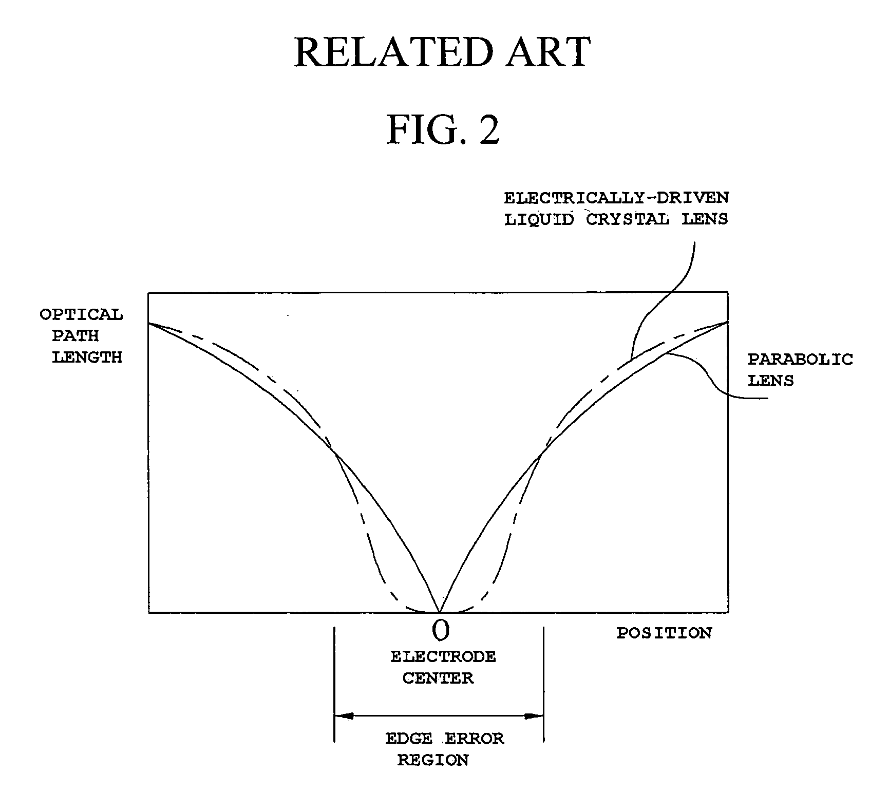
a liquid crystal lens and electric drive technology, applied in the direction of optics, instruments, optical elements, etc., can solve the problems of distorted image, phase plane seriously deviating from the profile of the parabolic lens, and difficulty in achieving the same phase plane as a parabolic using the electric drive liquid crystal lens when a voltage is applied to realize an image, etc., to achieve the effect of reducing crosstalk

Active Publication Date: 2009-01-15
LG DISPLAY CO LTD
View PDF4 Cites 42 Cited by
  • Summary
  • Abstract
  • Description
  • Claims
  • Application Information

AI Technical Summary

Benefits of technology

[0021]An advantage of the present invention is to provide an electrically-driven liquid crystal lens, which can reduce crosstalk caused at the center of an electrode, and a display device using the same.

Problems solved by technology

However, referring to FIG. 2, it can be appreciated that achieving the same phase plane as a parabolid using the electrically-driven liquid crystal lens when a voltage is applied to realize an image is difficult, and in particular, the phase plane seriously deviates from the profile of the parabolic lens at a section corresponding to the center of the first electrode, i.e. at a lens edge.
This may result in a distorted image upon realization of a 3-dimensional screen.
Upon formation of the electrically-driven liquid crystal lens, the lens edge has a seriously deviated phase from the profile of a lens having a physically formed parabolic or convex surface, causing distortion in the index of refraction for 3-dimensional imaging.
This results in crosstalk at the lens edge, making it impossible to display a normal image.

Method used


Image

  • Electrically-driven liquid crystal lens and display device using the same
  • Electrically-driven liquid crystal lens and display device using the same
  • Electrically-driven liquid crystal lens and display device using the same

Examples


Embodiment Construction

[0037]Reference will now be made in detail to an embodiments of the present invention, examples of which are illustrated in the accompanying drawings. Wherever possible, the same reference numbers will be used throughout the drawings to refer to the same or like parts.

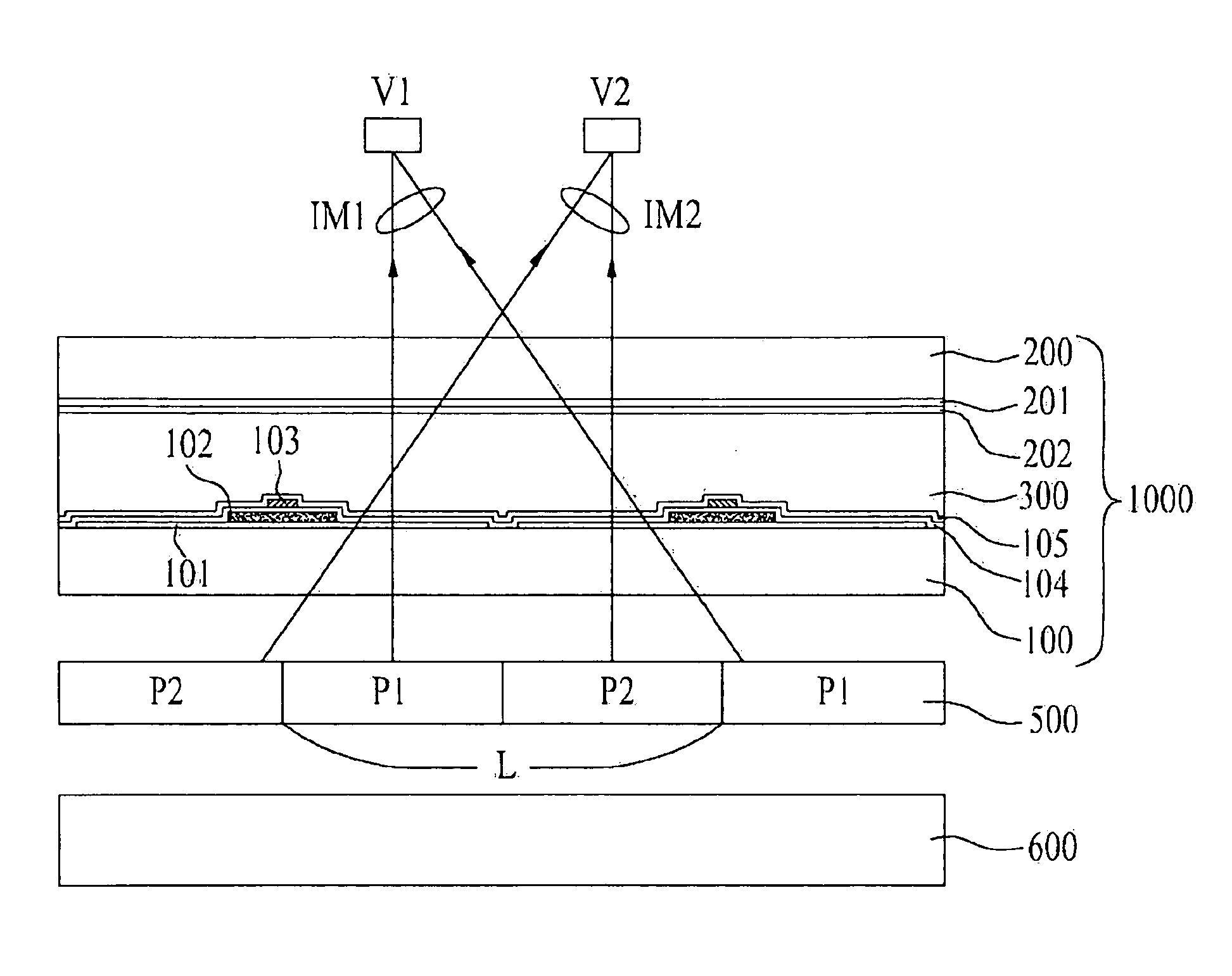
[0038]FIG. 3 is a plan view illustrating an electrically-driven liquid crystal lens, and FIG. 4 is a structural sectional view taken along the line I-I′ of FIG. 3.

[0039]As shown in FIGS. 3 and 4, the electrically-driven liquid crystal lens, which is designated by reference numeral 1000, includes first and second substrates 100 and 200 arranged opposite each other and formed at their corresponding positions with lens regions L, and a liquid crystal layer 300 interposed between the first substrate 100 and the second substrate 200. Here, the plurality of lens regions L are formed at both the first and second substrates 100 and 200, respectively, to correspond to each other. The respective lens regions L are defined to hav...


PUM

PropertyMeasurementUnit
voltageaaaaaaaaaa
thicknessaaaaaaaaaa
electrically-aaaaaaaaaa

Abstract

An electrically-driven liquid crystal lens, which can reduce crosstalk caused at the center of an electrode, and a display device using the same are disclosed. The electrically-driven liquid crystal lens includes first and second substrates arranged opposite each other and defined, respectively, with a plurality of lens regions corresponding to each other, first electrodes formed on the first substrate between centers of the respective neighboring left and right lens regions on the first substrate, a black matrix layer formed on the first substrate to correspond to edges of the respective lens regions, the black matrix layer having a first width, second electrodes formed on the first substrate to correspond to the edges of the respective lens regions, the second electrodes having a second width smaller than the first width, a third electrode formed throughout the second substrate, and a liquid crystal layer interposed between the first substrate and the second substrate.

Description

[0001]This application claims the benefit of the Korean Patent Application No. P2007-067519, filed on Jul. 5, 2007, which is hereby incorporated by reference for all purposes as if fully set forth herein.BACKGROUND OF THE INVENTION[0002]1. Field of the Invention[0003]The present invention relates to an electrically-driven liquid crystal lens, and more particularly, to an electrically-driven liquid crystal lens, which can reduce crosstalk caused at the center of an electrode, and a display device using the same.[0004]2. Discussion of the Related Art[0005]Nowadays, services for rapid dissemination of information, which will be constructed on the basis of high-speed information communication networks, have been developed from a simple “listening and speaking” service, such as current telephones, to a “watching and listening” multimedia type service on the basis of digital terminals used for high-speed processing of characters, voice and images, and are expected to be ultimately develop...

Claims


Application Information

Patent Timeline
Patent Type & Authority Applications(United States)
IPC IPC(8): G02F1/1335G02F1/13G02B30/28
CPCG02B27/2214G02F1/29G02F1/134309G02F1/133512G02B30/28G02F1/1335G02B30/27
Inventor SHIN, HYON HOJUNG, SUNG MIN
Owner LG DISPLAY CO LTD
Why Eureka
Try Eureka