Projector device, laminate type light-emitting diode device, and reflection type light-emitting diode unit

a technology of light-emitting diodes and projectors, which is applied in the direction of semiconductor devices for light sources, lighting and heating devices, instruments, etc., can solve the problem of cumbersome device construction

Inactive Publication Date: 2009-01-15
IWASAKI ELECTRIC CO LTD
View PDF5 Cites 4 Cited by
  • Summary
  • Abstract
  • Description
  • Claims
  • Application Information

AI Technical Summary

Benefits of technology

[0020]According to the present invention, the laminate type light emitting diode device in which the reflection type light emitting diode units of at least red light, green light and blue light are joined to one another so s to emit the respective light in the same direction is used as the light source. Therefore, when the light source is disposed in the projector device, a work of matching the optical axes of the reflection type light emitting diode units with one another is unnecessary.

Problems solved by technology

When white light is used as a light source, it is necessary that a filter member for dividing the white light into three colors of R, G and B between the light source and the optical modulator, and the construction of the device is cumbersome.

Method used


Image

  • Projector device, laminate type light-emitting diode device, and reflection type light-emitting diode unit
  • Projector device, laminate type light-emitting diode device, and reflection type light-emitting diode unit
  • Projector device, laminate type light-emitting diode device, and reflection type light-emitting diode unit

Examples


first embodiment

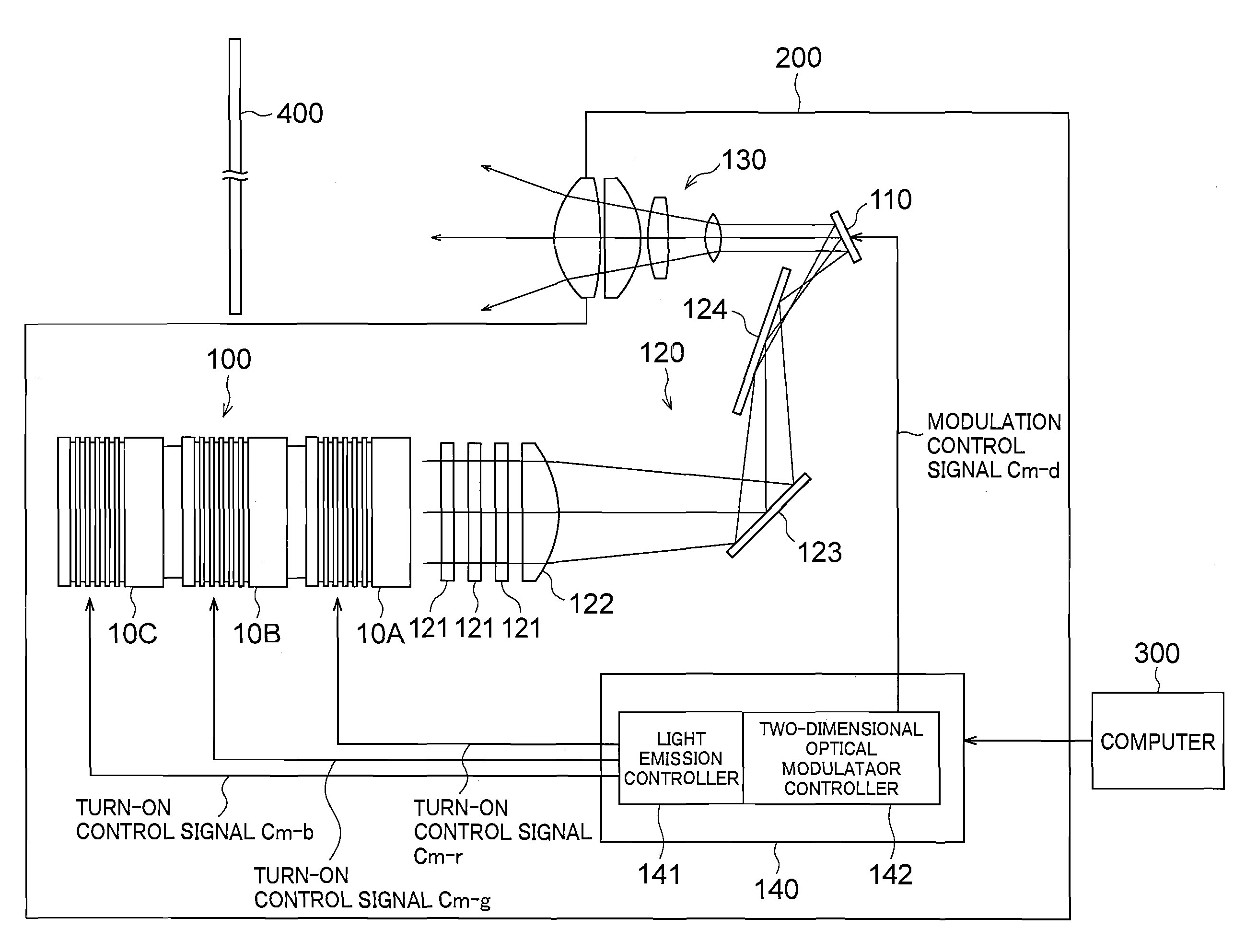
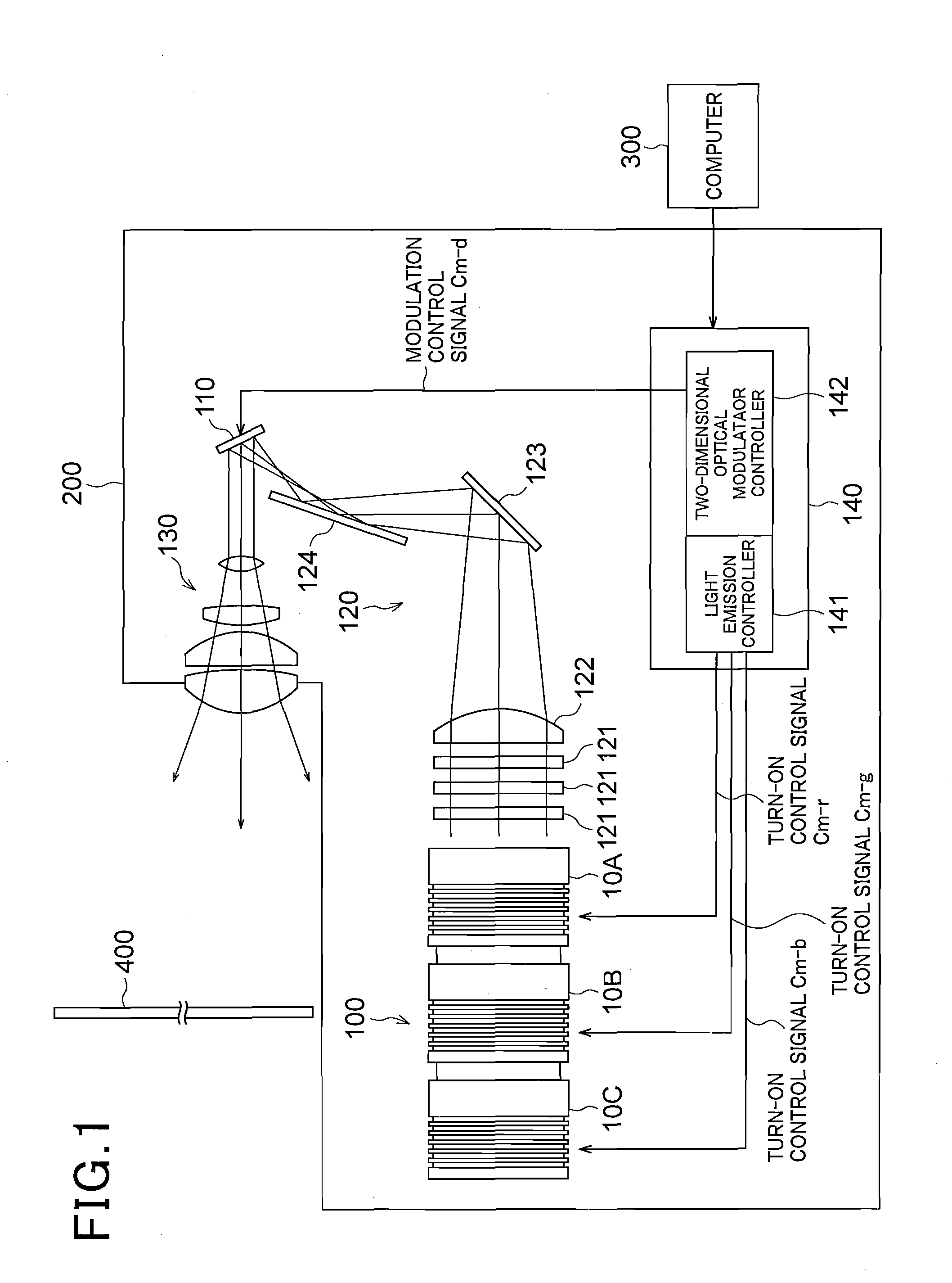
[0022]FIG. 1 is a schematic diagram showing the construction of a projector device 200 according to an embodiment. As shown in FIG. 1, the projector device 200 is equipped with a laminate type light emitting diode device 100 as a light source for emitting light, a two-dimensional optical modulator 110 for modulating light, a irradiating optical system 120 for guiding light emitted from the laminate type light emitting diode device 100 to the two-dimensional optical modulator 110, a projecting optical system 130 for projecting the modulated light modulated in the two-dimensional optical modulator 110, and a control device 140 for executing the control of the operation of the projector device 200.

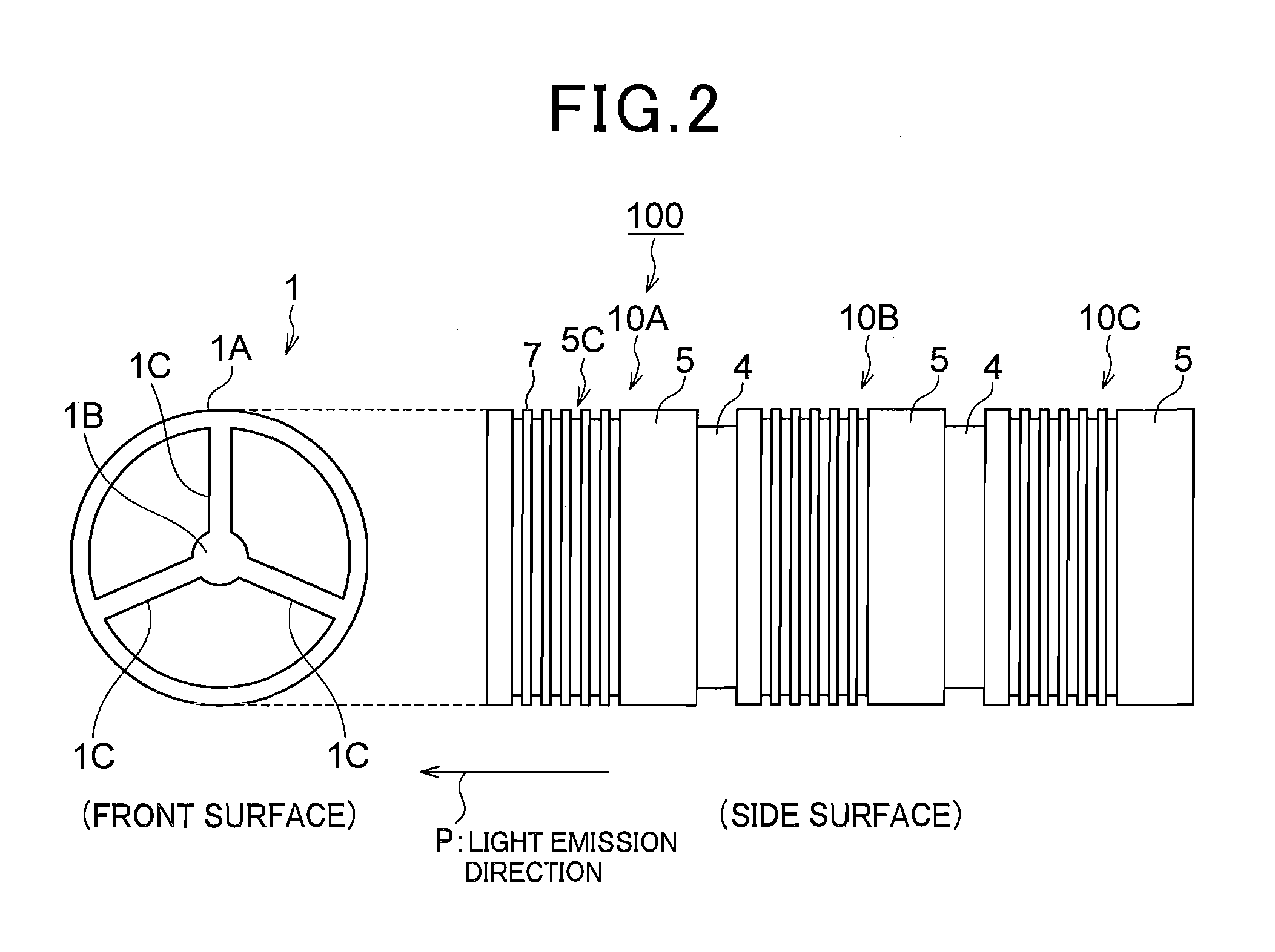
[0023]The laminate type light emitting diode device 100 selectively emits red light (R), green light (G) and blue light (B) corresponding to the three primary colors or emits some of the red, green and blue light (containing a case where all color light is emitted) at the same time. Specifica...

second embodiment

[0086]In the first embodiment described above, the plural reflection type light emitting diodes 10A to 10C of the laminate type light emitting diode device 100 are individually or simultaneously turned on, and an image is projected by using the color light represented in the range shown in the xy chromaticity diagram of FIG. 14. On the other hand, according to this embodiment, a laminate type light emitting diode device 100A in which a light emitting diode unit 10D for emitting light different from R, G, B light (hereinafter referred to “another color light”) is further joined to the reflection type light emitting diode units 10A to 10C is used as a light source to project an image.

[0087]That is, in the projector device 200A, an image is represented by using color represented in the composite range of four colors of the reflection type light emitting diode units 10A to 10D as shown in the xy chromaticity diagram of FIG. 16. Specifically, as shown in FIG. 17, four periods of the R li...


PUM


Abstract

A laminate type light emitting diode device having excellent heat radiation performance and high output capability is provided. A plurality of reflection type light emitting diode units 10 each of which includes a light emitting diode 2 and a dichroic mirror 3 in a hollow metal holder case 5 having high thermal conductivity so as to face each other are joined to one another through joint members 4 formed of electrical insulating material, thereby constructing the laminate type light emitting diode device 100.

Description

TECHNICAL FIELD[0001]The present invention relates to a projector device for projecting and displaying an image on a screen or the like, for example, and a laminate type light emitting diode device and a reflection type light emitting diode unit that are suitably used for the projector device.BACKGROUND ART[0002]There is known a projector device in which light emitted from a light source is modulated by using an optical modulator such as DMD (digital mirror device: registered trademark) or the like, and the modulated light is enlarged and projected onto a screen by using a projection lens. In this type projector device, a white discharge lamp such as a super-high pressure mercury lamp, a xenon lamp or the like is used as a light source (for example, see Patent Document 1). However, it is general in the projector device that images of red (R), green (G) and blue (B) corresponding to three primary colors are time-divisionally projected during one frame. When white light is used as a l...

Claims


Application Information

Patent Timeline
Patent Type & Authority Applications(United States)
IPC IPC(8): G03B21/00F21V7/00
CPCF21V29/004G03B21/14G02B5/10F21Y2101/02F21V29/74F21Y2115/10G03B21/2013G03B21/2033G03B33/12
Inventor HATANAKA, MITSUYUKISATO, TAKASHIYAMAMOTO, KAZUOSAITO, YUKIMASAUCHIDA, KOJIKAWANABE, YASUFUMI
Owner IWASAKI ELECTRIC CO LTD
Why Eureka
Try Eureka