Method for manufacturing heat radiator having plate-shaped fins

a technology of heat radiator and fin, which is applied in the field of heat radiator, can solve the problems of difficult scrapping of fin, inability to gouge out the radiating fin, and inability to remove thin, and achieve the effect of high efficiency and heat radiation

Inactive Publication Date: 2013-03-05
NAKAMURA SEISAKUSHO KK
View PDF13 Cites 2 Cited by
  • Summary
  • Abstract
  • Description
  • Claims
  • Application Information

AI Technical Summary

Benefits of technology

[0031]In accordance with the method for manufacturing a heat radiator having plate-shaped fins of the present invention, a cutting tool is inserted at a prescribed position set at a distance from one end of the metal plate to form small fins having a small dimension, the base end of which is integrally connected to the metal plate. Therefore, the formation of thin scrap fins is prevented in advance. Accordingly, the work of removing scrap is made unnecessary, and problems are solved in which the deformation of heat radiating fins occurs and fins cannot be formed by gouging due to scrap adhering to the metal plate or the cutting tool.
[0032]A plurality of small fins is sequentially formed with an increasing size from the prescribed position set at a distance from one end of the metal plate to the position of the heat-radiating fins, whereby sloped surfaces are formed by the apices of the plurality of small fins. Therefore, a cooling medium is more readily received from the small fin side and a heat radiator having highly efficient heat radiation can be formed.
[0033]In the fin formation step, the plate thickness of the cut fins toward the base ends thereof is formed to be great, whereby the cut fins are widened at least at the two ends on the base-end side. Therefore, the two ends of the base portion of the heat-radiating fins are pressed by the interior wall of the concavity, the heat of the metal plate is conducted to the two ends as well, and a heat radiator having highly efficient heat radiation can be formed.
[0034]The width of the gouging tool is formed to be less than the width of the metal plate, whereby a flange part having the thickness of the metal plate can be formed on the two sides of the plurality of heat-radiating fins. The flange part may have a heat radiator mounted thereon, or may be provided with a covering material on the upper portion of heat radiating fins, and constitutes part of a heat pump, a vapor chamber, or another liquid-cooled heat exchanger.

Problems solved by technology

In the method of forming plate-shaped heat-radiating fins disclosed in Patent Document 2 as well, there are occasions when removing thin, fin-shaped scrap becomes difficult in the same way as in Patent Document 1 because low fin-shaped scrap is generated at one end of the metal plate on hoop-shaped metal plate when heat-radiating fins are formed from one end of the hoop-shaped metal plate.
Accordingly, the fin-shaped scraps are sandwiched between the surface of the hoop-shaped metal plate and the cutting tool, and a problem occurs in that the heat-radiating fin that is subsequently formed is formed in a deformed state, or a problem occurs in that the next heat-radiating fin cannot be gouged out.

Method used


Image

  • Method for manufacturing heat radiator having plate-shaped fins
  • Method for manufacturing heat radiator having plate-shaped fins
  • Method for manufacturing heat radiator having plate-shaped fins

Examples


embodiment 1

(Embodiment 1)

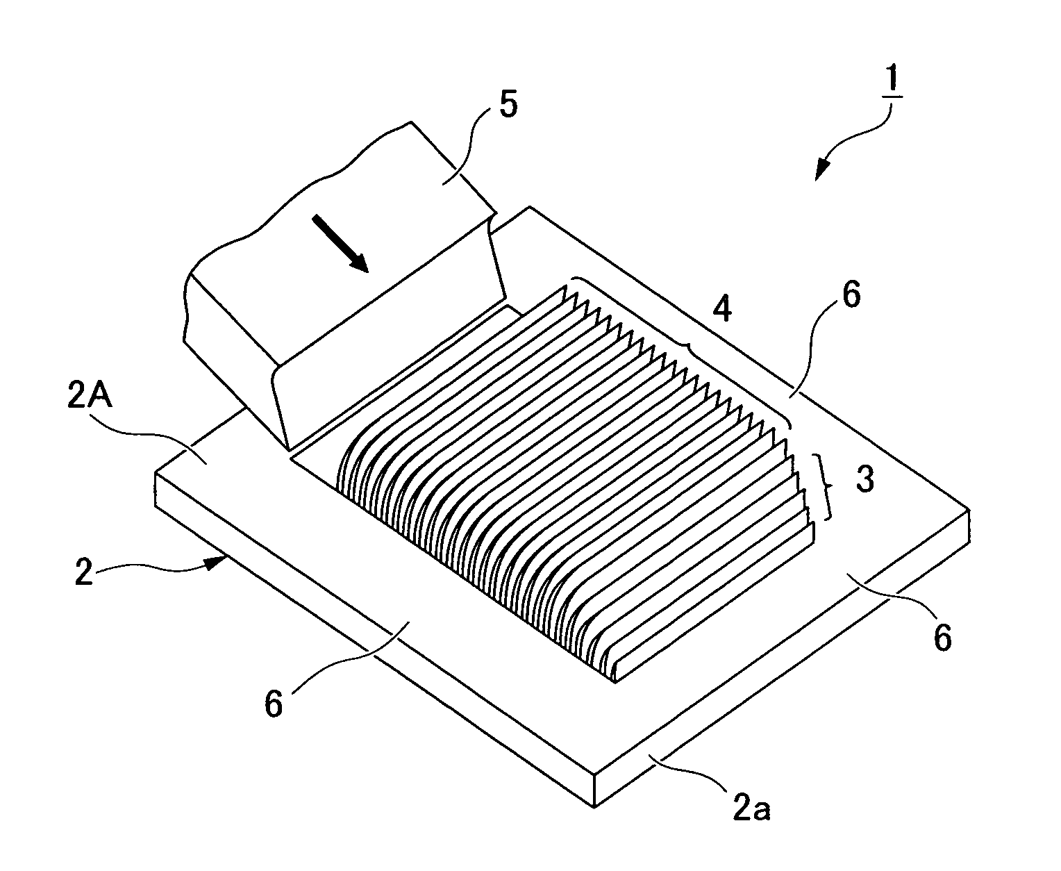
[0044]FIG. 1 is a perspective view showing a heat radiator having plate-shaped heat-radiating fins according to Embodiment 1. A plastically workable metal material having a high coefficient of thermal conductivity can be used for the metal plate 2 used in a heat radiator 1. For example, it is possible to use a rectangular metal plate 2 having a uniform thickness and formed from aluminum, aluminum alloy, copper alloy, stainless steel, or another metal material.

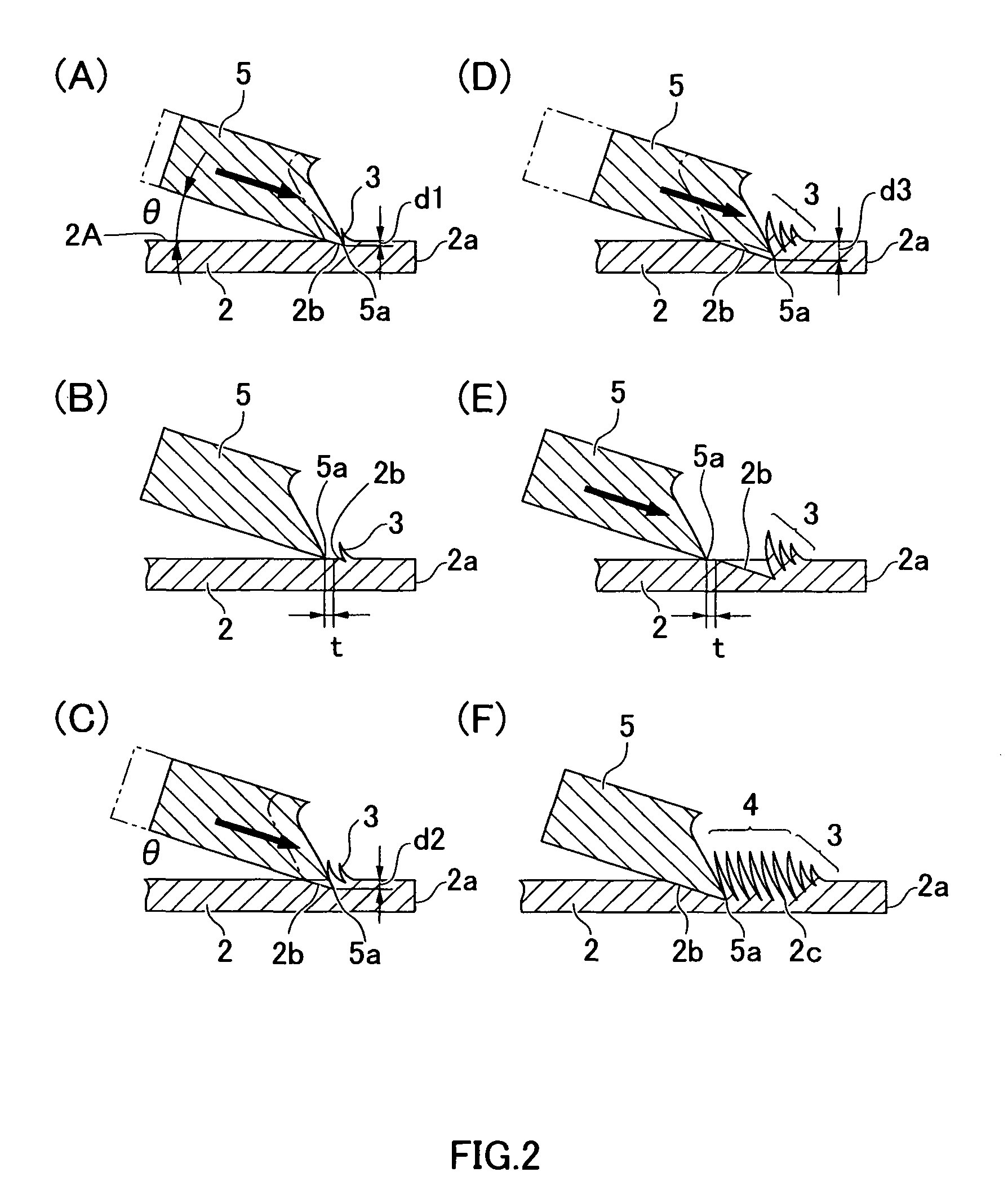
[0045]A plurality of small, low fins 3 is formed in a section (at a prescribed position set at a distance from one end of the metal plate) located inward from an outside edge 2a of a surface 2A (one of the surfaces) of the metal plate 2. Subsequent to these small fins 3, thin plate-shaped heat-radiating fins 4 having the same height are formed. The small fins 3 are formed from one outside edge 2a of the metal plate 2 so as to gradually increase in height until the heat-radiating fins 4 are reached. The base-end po...

embodiment 2

(Embodiment 2)

[0064]FIG. 5 shows an example in which a hoop-shaped metal plate 10 is used as the metal plate in the method for manufacturing a heat radiator having plate-shaped fins according to the present invention. The hoop-shaped metal plate 10 can be plastically worked in the same manner as in Embodiment 1 described above, and aluminum, aluminum alloy, copper alloy, stainless steel, or another metal material is used as the metal material having a high coefficient of thermal conductivity.

[0065]A plurality of heat-radiating fins 4 is formed subsequent to the formation of the plurality of small fins 3 in the same manner as in Embodiment 1 described above on the hoop-shaped metal plate 10 as well, to form a first fin group 11. A plurality of heat-radiating fins 4 is formed subsequent to the formation of the plurality of small fins 3 to form a second fin group 12 separated by spaces 13 at prescribed intervals, and fin groups are sequentially formed while providing the spaces 13 at p...

embodiment 3

(Embodiment 3)

[0067]FIG. 6 shows an embodiment in which a pair of fin groups on the left and right are formed by forming a plurality of small fins from the center of the metal plate, followed by a plurality of heat-radiating fins in the method for manufacturing the heat radiator having plate-shaped fins according to the present invention.

[0068]In the embodiment shown in FIG. 6, the blade section of the gouging tool 5 is brought into contact with a prescribed position at the center of the metal plate 20 in the same manner as in the formation method shown in FIG. 2 described above, the blade section 5a of the gouging tool 5 is thereafter made to bite into a surface of the metal plate 20 at a prescribed angle, and a thin small fin 3 having a low profile is formed upright. Afterward, the small fin is formed upright a plurality of times until the blade section 5a of the gouging tool 5 reaches a prescribed depth. A transition is thereafter made to the fin formation step subsequent to the ...


PUM

PropertyMeasurementUnit
widthaaaaaaaaaa
gouging widthaaaaaaaaaa
thicknessaaaaaaaaaa

Abstract

A gouging tool is introduced at a slope angle θ to form small, low fins at a position shifted inward from an edge of a surface of a metal plate having a high coefficient of thermal conductivity; and the small fins are sequentially formed in a plural number at a fixed pitch until a blade section of the gouging tool reaches a prescribed depth. A fin formation step in which plate-shaped heat-radiating fins are integrally formed upright by the gouging tool is subsequently repeated in sequential manner following formation of the small fins, and the heat-radiating fins are continuously formed in a plural number in the metal plate. Heat-radiating fins of a heat radiator can be formed by a gouging tool without generating scrap.

Description

TECHNICAL FIELD[0001]The present invention relates to a heat radiator for efficiently radiating heat that is generated in, e.g., electronic components and the like, and specifically relates to a method for manufacturing a heat radiator having plate-shaped fins integrally formed on a metal plate via a cutting tool.BACKGROUND ART[0002]Ordinary heat radiators that are used in actual practice for radiating heat generated in semiconductor ICs and other electronic components have a plurality of pectinate heat-radiating fins formed perpendicularly on a base. The heat radiator radiates heat outward via the heat-radiating fins of the heat radiator by direct or indirect contact with an electronic component or the like. The heat radiator is generally manufactured by extruding or casting an aluminum metal material having a high coefficient of thermal conductivity.[0003]Methods of manufacturing heat radiators on which heat-radiating fins are formed by using a cutting tool are disclosed in JP-A 2...

Claims


Application Information

Patent Timeline
Patent Type & Authority Patents(United States)
IPC IPC(8): B21D53/02B23P13/00
CPCB23P15/26F28F3/048H01L21/4878H01L23/3672B23P2700/10Y10T29/49389H01L2924/0002Y10T29/49995Y10T29/4935H01L2924/00B21J5/068
Inventor MIYAHARA, HIDEYUKI
Owner NAKAMURA SEISAKUSHO KK
Why Eureka
Try Eureka