
Magnet assisted stage for vibration and heat reduction in wafer scanning

a technology of wafer scanning and assisted stage, which is applied in the direction of photomechanical equipment, instruments, machine supports, etc., can solve the problems of increasing thermal errors, increasing design complexity, increasing costs, etc., and achieves the effects of reducing residual vibration, enhancing scanning speed, and reducing motor heat and residual vibration

Active Publication Date: 2017-03-30
RGT UNIV OF MICHIGAN
View PDF3 Cites 3 Cited by
  • Summary
  • Abstract
  • Description
  • Claims
  • Application Information

AI Technical Summary

Benefits of technology

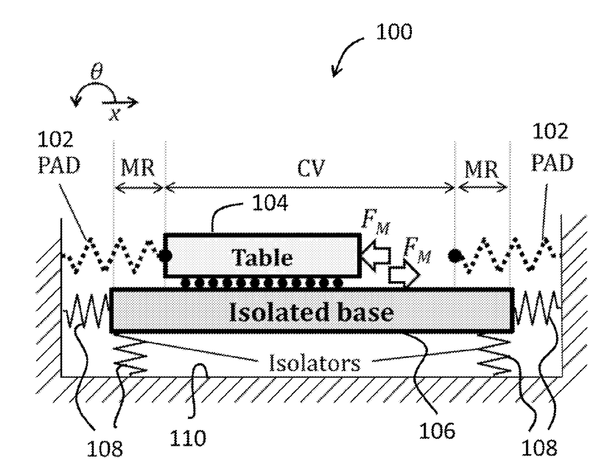
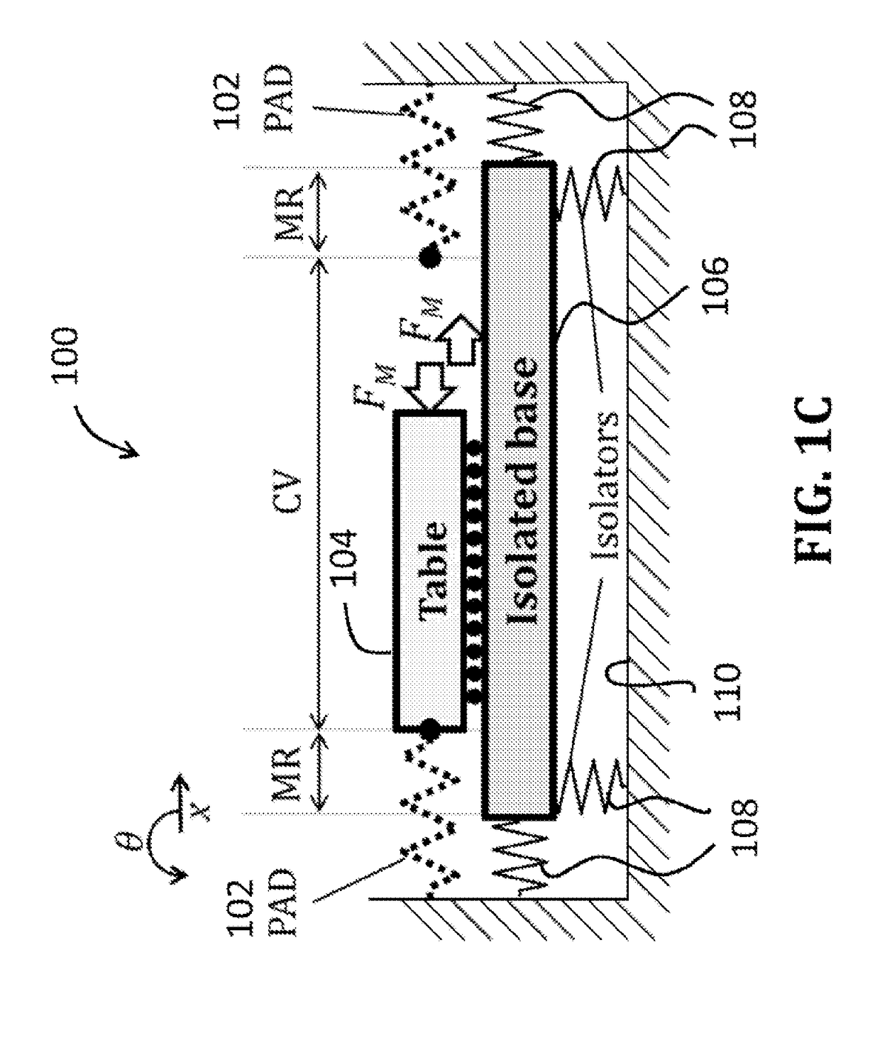
The patent text describes a method to reduce heat and vibration in a scanning stage system. The method uses a passive assist device that stores and releases energy during motion reversals to lower the required force for acceleration and deceleration. The assist device reduces the current and power needed for the motor, but its effectiveness depends on the specific motion trajectory it is designed for. The system uses a pair of repelling permanent magnets (PMs) that are adjusted to minimize heat and vibration. The PMs are positioned to reduce heat transmitted to the table and vibration transmitted to the ground during high-speed scanning. The method has been tested on a prototype stage and results show significant reductions in vibration and heat.

Problems solved by technology

The resulting high inertial forces that are borne by the linear motor actuators cause Joule heating proportional to the square of the motor current, leading to increased thermal errors.
Unfortunately, forced cooling requires cooling circuits and external heat exchangers, which add to design complexities and raise costs.
Light-weighting could reduce structural stiffness and introduce unwanted vibrations.
Control techniques can only offer incremental benefits for a given motor design.
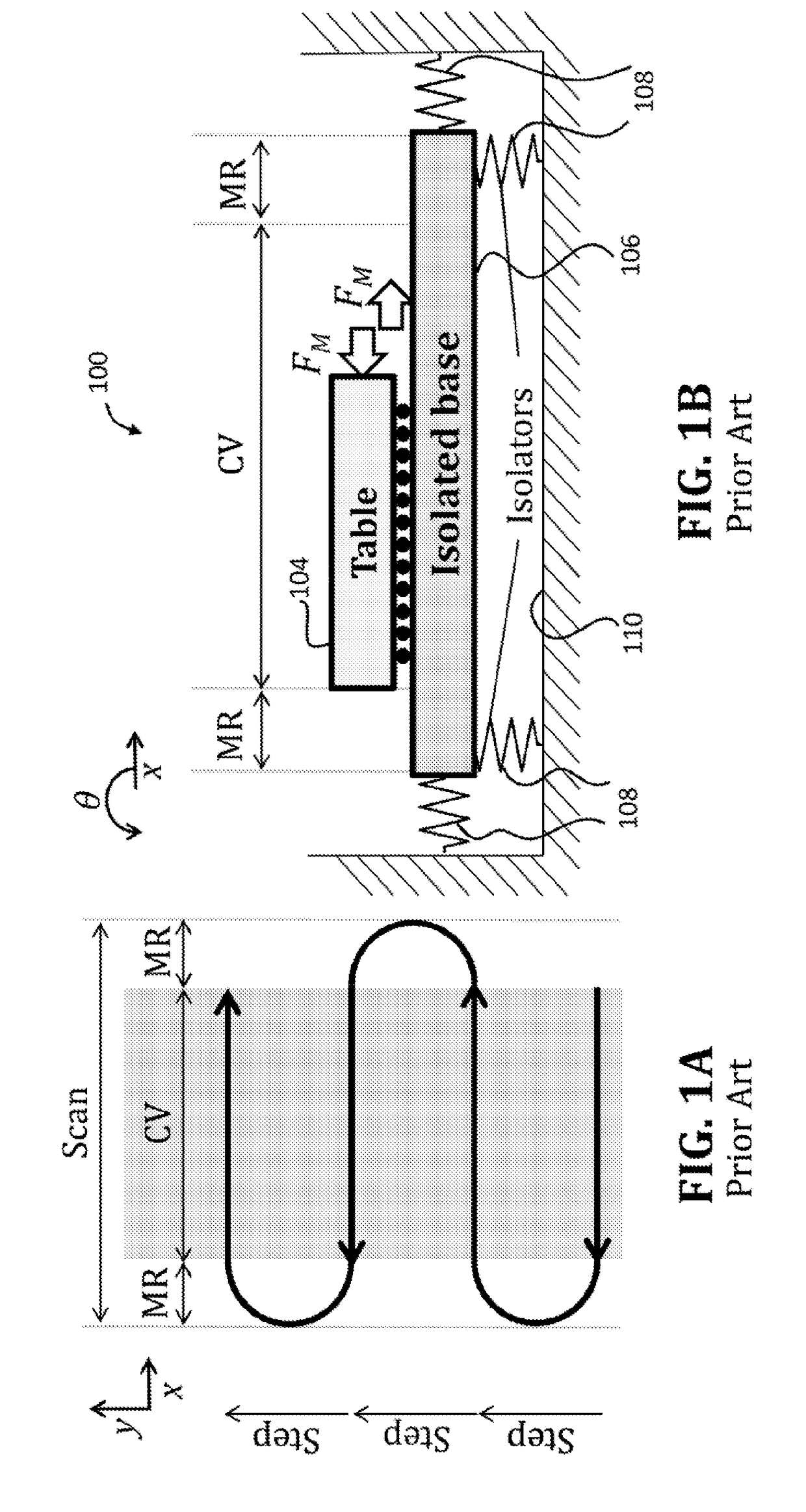
In addition to generating excessive heat, the high inertial forces in scanning stages cause residual vibration of the machine frame, which adversely affects positioning speed and precision.
Tuned mass dampers and input shapers lose effectiveness when operating conditions change.
Counter motion devices are bulky, expensive and energy intensive.
However, the passive assist device could increase motor currents / heat for operating conditions other than the ones for which it was tuned, making it limited in versatility.

Method used


Image

  • Magnet assisted stage for vibration and heat reduction in wafer scanning
  • Magnet assisted stage for vibration and heat reduction in wafer scanning
  • Magnet assisted stage for vibration and heat reduction in wafer scanning

Examples


Embodiment Construction

[0029]Example embodiments will now be described more fully with reference to the accompanying drawings. Example embodiments are provided so that this disclosure will be thorough, and will fully convey the scope to those who are skilled in the art. Numerous specific details are set forth such as examples of specific components, devices, and methods, to provide a thorough understanding of embodiments of the present disclosure. It will be apparent to those skilled in the art that specific details need not be employed, that example embodiments may be embodied in many different forms and that neither should be construed to limit the scope of the disclosure. In some example embodiments, well-known processes, well-known device structures, and well-known technologies are not described in detail.

[0030]The terminology used herein is for the purpose of describing particular example embodiments only and is not intended to be limiting. As used herein, the singular forms “a,”“an,” and “the” may b...


PUM

PropertyMeasurementUnit
magnetic forceaaaaaaaaaa
stiffnessaaaaaaaaaa
spring stiffnessaaaaaaaaaa

Abstract

A magnet assisted stage system for scanning applications having a scanning table being moveable from a first position to a second position, a scanning actuator operably associated with the scanning table to move the scanning table along a scanning direction from the first position to the second position, and an actively variable magnetic spring system being operably augmented to the scanning table to exert a magnetic repulsion force upon the scanning table in the scanning direction.

Description

CROSS-REFERENCE TO RELATED APPLICATIONS[0001]This application claims the benefit of U.S. Provisional Application No. 62 / 008,978, filed on Jun. 5, 2014. The entire disclosure of the above application is incorporated herein by reference.GOVERNMENT INTEREST[0002]This invention was made with government support under CMM11350202, awarded by the National Science Foundation. The Government has certain rights in the invention.FIELD[0003]The present disclosure relates to an active assist stage for scanning applications and, more particularly, to a magnet assisted stage for vibration and heat reduction in wafer scanning.BACKGROUND AND SUMMARY[0004]This section provides background information related to the present disclosure which is not necessarily prior art. This section also provides a general summary of the disclosure, and is not a comprehensive disclosure of its full scope or all of its features.[0005]Scanning stages are used for precise positioning in a variety of advanced manufacturing...

Claims


Application Information

Patent Timeline
Patent Type & Authority Applications(United States)
IPC IPC(8): F16M11/04F16M11/18G03F7/20H01L21/67
CPCF16M11/043H01L21/67259G01N2201/103G03F7/709G01N21/9501F16M11/18H01L21/68G03F7/70758G03F7/70858
Inventor OKWUDIRE, CHINEDUM E.YOON, DEOKKYUN D.
Owner RGT UNIV OF MICHIGAN
Learn More