Engine cooling apparatus

a cooling apparatus and engine technology, applied in the direction of engine cooling apparatus, machine/engine, measurement device, etc., can solve the problems of increased cavitation probability, reduced engine output, increased cavitation probability, etc., to achieve sufficient cooling performance, reduce the flow resistance of the cooling water circuit, and suppress the effect of knocking

Inactive Publication Date: 2012-02-02
YAMADA SEISAKUSHO KK
View PDF0 Cites 2 Cited by
  • Summary
  • Abstract
  • Description
  • Claims
  • Application Information

AI Technical Summary

Benefits of technology

[0010]The present invention has been designed in consideration of these problems, and an object thereof is to provide an engine cooling apparatus that is capable of suppressing cavitation in a high rotation region of an engine while maintaining a cooling capability in an intermediate rotation region of the engine.
[0012]A second invention according to claim 1 solves the problems described above by providing an engine cooling apparatus that performs control for reducing the predetermined rotation speed as the temperature of the cooling water detected by the temperature detecting means increases.
[0013]With the constitution of the first invention, when the rotation speed of the engine falls to or below the predetermined rotation speed, the control valve in the second bypass flow passage is set in a fully open state, whereby the second bypass flow passage is set in the circulation state in which the cooling water flows. Accordingly, the flow resistance of the cooling water circuit decreases, leading to an increase in the amount of cooling water circulating through the engine, and as a result, a sufficient cooling performance can be secured and knocking can be suppressed.
[0014]With a conventional device such as that described above, when the rotation speed of the engine increases to a high rotation state while the control valve remains fully open, the discharge flow rate of the water pump becomes excessively large, leading to a reduction in the internal pressure of the flow passage oh the water pump suction side, and as a result, cavitation may occur. When the rotation speed of the engine detected by the engine rotation speed detecting means reaches or exceeds the predetermined rotation speed in the present invention, the opening of the control valve is controlled in the fully closed direction in accordance with the increase in the rotation speed. Therefore, when the rotation speed of the engine is in a high rotation region, the flow resistance increases such that the cooling water circulation amount can be suppressed, and as a result, cavitation can be suppressed.
[0015]Further, when the rotation speed of the engine is equal to or higher than the predetermined rotation speed, the control valve is controlled gradually in the fully closed direction from the fully open state in accordance with the increase in the rotation speed, and therefore, in contrast with a case where the control valve is set only in the fully open state and the fully closed state, the flow rate of the cooling water supplied to the engine is appropriate for the rotation speed of the engine. As a result, unnecessary work by the water pump can be eliminated. Furthermore, the first bypass flow passage is not modified from that of the related art, and therefore travel remains possible even if a defect occurs in the second bypass flow passage, albeit with a slightly poorer fuel efficiency.
[0016]With the constitution of the second invention, the predetermined rotation speed for controlling the opening of the control valve is controlled to be steadily lower as the cooling water temperature rises. Lowering the predetermined rotation speed means lowering the rotation speed of the engine at which control of the control valve in the fully closed direction from the fully open state begins. As the water temperature increases, a rotation speed range in which cavitation occurs tends to shift to a low rotation side, and therefore, by lowering the predetermined rotation speed, cavitation can be suppressed.

Problems solved by technology

As a result, the internal pressure of the suction side flow passage of the water pump may decrease, leading to an increase in the likelihood of cavitation.
If the discharge flow rate of the water pump is reduced to ensure that cavitation does not occur in the high rotation region of the engine, however, knocking becomes more likely to occur when the engine performs a high load operation in a low rotation region, and as a result, an engine output may decrease.

Method used


Image

  • Engine cooling apparatus
  • Engine cooling apparatus
  • Engine cooling apparatus

Examples


Embodiment Construction

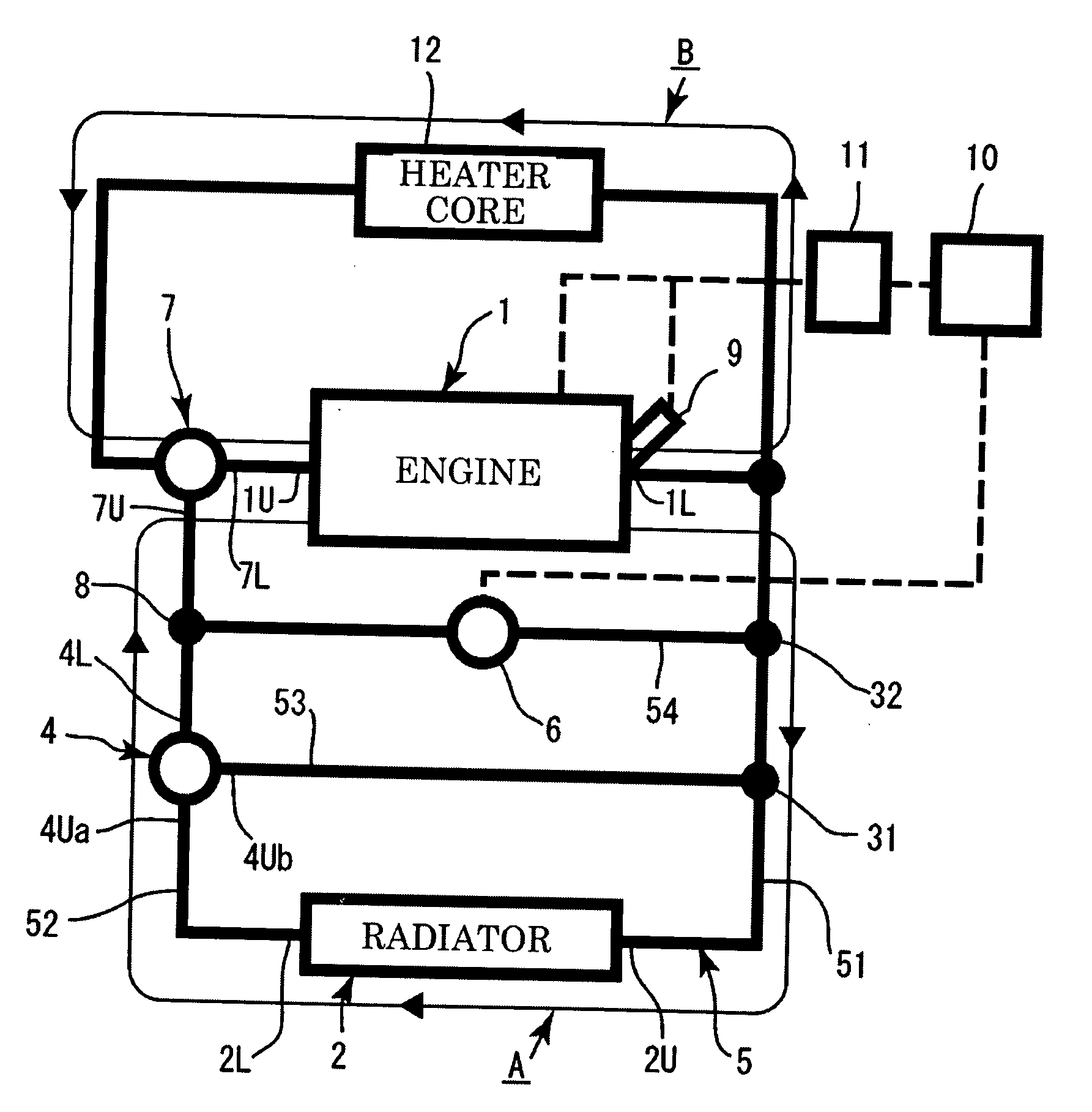
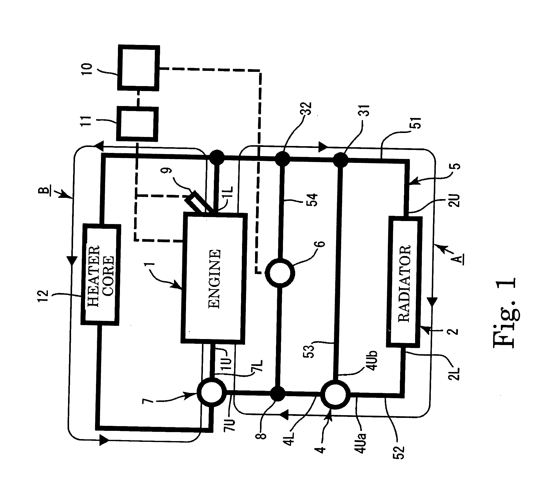
[0019]An embodiment of the present invention will be described below on the basis of the drawings. The present invention is a circuit for circulating cooling water between an engine 1 and a radiator 2, which is mainly constituted by a main cooling water circuit A, a first bypass flow passage 53, and a second bypass flow passage 54. A heater circuit B having a flow passage that passes through an engine 1 and a heater core 12 provided in the flow passage is provided in addition to the main cooling water circuit A.

[0020]FIG. 1 shows the cooling water circuit according to the present invention. In the following description, a side of internal components of the cooling water circuit such as the radiator 2 and a thermostat 4 on which the cooling water flows into the components will be referred to as an upstream side and indicated by affixing a reference symbol “U” to the respective components, and a side on which the cooling water flows out of the components will be referred to as a downs...


PUM


Abstract

The present invention provides an engine cooling apparatus that is capable of suppressing cavitation in a high rotation region while achieving an increase in a circulation flow rate of cooling water in a low / medium rotation region. The engine cooling apparatus includes: a main cooling water circuit that circulates the cooling water between an engine and a radiator; a branch portion provided between the engine and the radiator; a thermostat; temperature detecting means; a first bypass flow passage; a second bypass flow passage that connects the engine to the branch portion; a control valve; a bypass convergence portion; a water pump; valve opening control means; and engine rotation speed detecting means.

Description

BACKGROUND OF THE INVENTION[0001]1. Field of the Invention[0002]The present invention relates to an engine cooling apparatus that achieves an increase in a circulation flow rate of cooling water in a low / medium rotation region while suppressing cavitation in a high rotation region.[0003]2. Description of the Related Art[0004]In a conventional cooling water circuit provided with a bypass circuit for circulating cooling water flowing out of an engine to the engine while bypassing a radiator, two bypass circuits are provided in parallel, a valve is provided in one of the two bypass circuits, and by opening the valve when an engine rotation speed is high in order to reduce a flow passage resistance, an attempt is made to prevent cavitation.[0005]In Japanese Patent Application Publication No. 2007-100659, for example, a first bypass passage (7) and a second bypass passage (10) are connected in parallel so as to bypass a radiator (2), and a solenoid control valve (11) is disposed at a mid...

Claims


Application Information

Patent Timeline
Patent Type & Authority Applications(United States)
IPC IPC(8): F01P7/16F01P7/00
CPCF01P7/165F01P2060/08F01P2025/64F01P7/167
Inventor KOYASHIKI, HIDEHIKOKOBAYASHI, TAKESHIMIKUNI, TAKAHIRO
Owner YAMADA SEISAKUSHO KK
Why Eureka
Try Eureka