Transmitting apparatus, receiving apparatus, error correcting system, transmitting method, and error correcting method

a technology of error correction system and transmitting method, which is applied in the field of transmission apparatus, receiving apparatus, error correction system, transmitting method, and error correction method, can solve the problems of unrestorable media packets, lost packets cannot be restored, etc., and achieve the effect of improving the recovery rate of lost media packets

Inactive Publication Date: 2009-01-15
SONY CORP
View PDF4 Cites 31 Cited by
  • Summary
  • Abstract
  • Description
  • Claims
  • Application Information

AI Technical Summary

Benefits of technology

[0010]In view of the above circumstances, it is desirable to provide a transmitting apparatus, a receiving apparatus, an error correcting system, a transmitting method, and an error correcting method capable of improving the restoration rate of lost packets.
[0035]As described above, according to the embodiments of the present invention, the restoration rate of lost packets can be improved.

Problems solved by technology

In the two-dimensional processing described in Japanese Patent Application Publication No. 2007-509557 (FIG. 1, etc.), however, for example, when four lost packets which form respective vertexes of a rectangle occur in the row and column directions, two lost packets occur in each of the row and column directions, whereby these lost packets cannot be restored even if any packet is used.
That is to say, by losing at least four media packets, all of these media packets may become unrestorable.

Method used


Image

  • Transmitting apparatus, receiving apparatus, error correcting system, transmitting method, and error correcting method
  • Transmitting apparatus, receiving apparatus, error correcting system, transmitting method, and error correcting method
  • Transmitting apparatus, receiving apparatus, error correcting system, transmitting method, and error correcting method

Examples


first embodiment

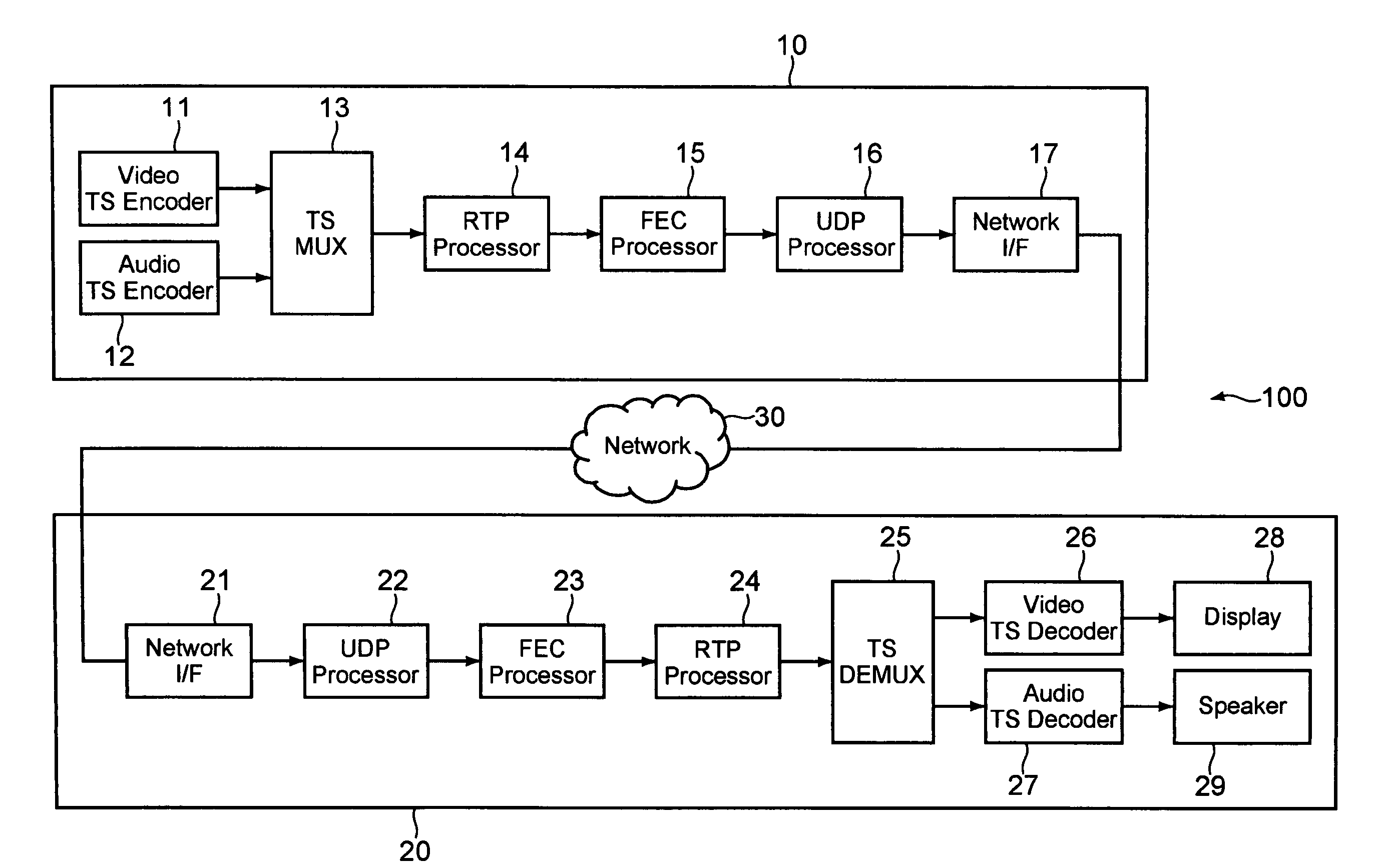
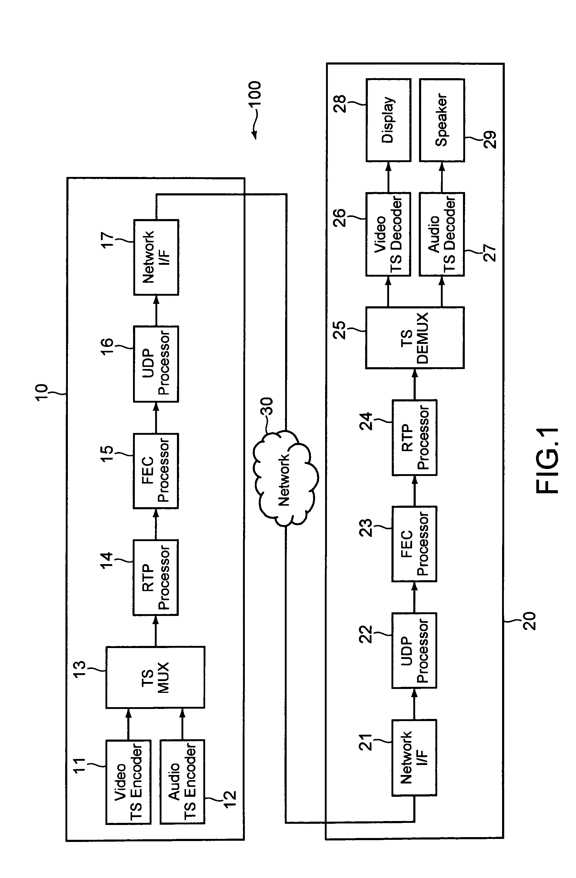
[0056]FIG. 1 is a diagram showing a configuration of an error correcting system according to a first embodiment of the present invention.

[0057]As shown in this figure, this error correcting system includes a server 10 serving as a transmitting apparatus and a television apparatus (hereinafter referred to as a TV) 20 serving as a receiving apparatus, both being connected to a network 30 such as the Internet, a leased line network, or a LAN (Local Area Network).

[0058]The server 10 includes a video TS (Transport Stream) encoder 11, an audio TS encoder 12, a TS-MUX (Multiplexer) 13, an RTP processor 14, an FEC processor 15, a UDP processor 16, and a network interface 17.

[0059]The video TS encoder 11 compression-encodes a video signal constituting a content as a video TS, for example, in a format such as MPEG (Moving Picture Expert Group)-2. The audio TS encoder 12 compression-encodes an audio signal constituting the content as an audio TS, for example, in a format such as MPEG-2. The TS...

second embodiment

[0096]Next, a second embodiment of the present invention will be described. Incidentally, in this embodiment, the same numerals and symbols will be given to portions having the same constitutions and functions as those in the above first embodiment, and descriptions thereof will be omitted or simplified. Further, also in this embodiment, as in the first embodiment, the server 10 and the TV 20 constitute the error correcting system 100, and in the following description, operations of the server 10 and the TV 20 will be mainly described.

[0097]FIG. 8 is a diagram showing a manner in which the FEC processor 15 of the server 10 generates the FEC packets 50 in this embodiment. Incidentally, in this embodiment, for convenience of description, a case where the media packets 40 are arranged in five rows and five columns is shown, but in actuality, the FEC packets 50 are generated with the packets 40 in 10 rows and 10 columns as one unit as in the first embodiment. Needless to say, the number...

third embodiment

[0119]Next, a third embodiment of the present invention will be described. Incidentally, in this embodiment, the same reference numerals and symbols will be given to portions having the same constitutions and functions as those in the above first and second embodiments, and descriptions thereof will be omitted or simplified. Further, also in this embodiment, as in the first and second embodiments, the server 10 and the TV 20 constitute the error correcting system 100, and in the following description, operations of the server 10 and the TV 20 will be mainly described.

[0120]In the above first and second embodiments, the media packets 40 are protected by one and two FEC packets 50, respectively. In these cases, however, the media packets 40 which are difficult to protect still exist. Hence, in this embodiment, the media packets 40 are protected by more FEC packets 50.

[0121]FIG. 12 is a diagram showing a manner in which the FEC processor 15 of the server 10 generates the FEC packets 50...


PUM


Abstract

A transmitting apparatus includes a generating unit and a transmitting unit. The generating unit generates first error correction packets by performing predetermined operation processing on a plurality of data packets arranged in a plurality of rows and columns respectively in each of the rows and columns and generating at least one second error correction packet by performing the predetermined operation processing on the data packets existing in a diagonal direction crossing the plurality of rows and columns. The transmitting unit transmits the plurality of data packets and the generated first and second error correction packets.

Description

CROSS REFERENCES TO RELATED APPLICATIONS[0001]The present invention contains subject matter related to Japanese Patent Application JP 2007-182294 filed in the Japanese Patent Office on Jul. 11, 2007, the entire contents of which being incorporated herein by reference.BACKGROUND OF THE INVENTION[0002]1. Field of the Invention[0003]The present invention relates to a transmitting apparatus transmitting error correction packets in addition to data packets, a receiving apparatus receiving the data packets and the error correction packets, an error correcting system using the transmitting apparatus and the receiving apparatus, a transmitting method performed in the transmitting apparatus, and an error correcting method performed in the receiving apparatus.[0004]2. Description of the Related Art[0005]In recent years, attention has been given to a television broadcasting service (IPTV) which provides contents using an IP (Internet Protocol) instead of airwaves. In this IPTV, in addition to ...

Claims


Application Information

Patent Timeline
Patent Type & Authority Applications(United States)
IPC IPC(8): H04L12/26H04L1/00H04L29/02
CPCH03M13/2909H03M13/2918H04L1/0057H03M13/293H03M13/2921
Inventor ICHIKI, SHOJI
Owner SONY CORP
Why Eureka
Try Eureka